As defined by ISO 2639 and GB/T 9450-2005 (Chinese national standard), effective case depth refers to the perpendicular distance from the part surface to the location where the Vickers hardness reaches the specified limit hardness (typically 550 HV for carburized parts and 400 HV for nitrided parts), measured in millimeters (mm).
It differs from total case depth (the distance from the surface to where hardness equals the core hardness). Effective case depth focuses on the load-bearing layer required for actual service:
- For carburized and quenched parts, the limit hardness is uniformly 550 HV (test force usually HV1 or HV0.5), the critical load-bearing hardness for steels under alternating load and wear conditions.
- For nitrided parts, the limit hardness is typically 400 HV, matching the high hardness and shallow depth of nitrided layers.
- Custom limit hardness is allowed per drawing for special conditions: up to 600 HV for high-load parts, down to 500 HV for light-load parts.


Specimen Preparation and Result Judgment
Effective case depth testing is centered on Vickers hardness testing, following a standardized workflow:
Specimen Preparation → Hardness Testing → Data Processing → Result Judgment
Each step directly affects measurement accuracy.
1. Specimen Preparation: Foundation of Testing Accuracy
The goal is to ensure a flat cross-section free of thermal damage and deformation to avoid hardness deviations:
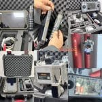
- Sampling: Cut perpendicular to the surface to include the full case and core; sample locations must comply with drawings (e.g., maximum-stress cross-sections, critical mating surfaces).
- Cutting: Prefer wire-cutting to avoid thermal damage from abrasive wheel cutting that causes abnormal hardness.
- Grinding and Polishing: Grind sequentially with 180#, 400#, 800#, 1200#, 2000# abrasive paper, then polish with diamond paste to eliminate scratches, edge rounding, and distortion.
- Etching (optional): Etch with 4% nital (nitric acid–alcohol) to clearly distinguish case and core, aiding test starting-point positioning and avoiding surface offset.
-2.jpg "What is Effective Case Depth? 5")
-1-300x87.jpg "What is Effective Case Depth? 6")
-3.jpg "What is Effective Case Depth? 7")
2. Hardness Testing: Core of Data Acquisition
Vickers hardness testing generates hardness-depth gradient data and must follow standards strictly:
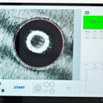
- Equipment: Use an automatic Vickers hardness tester. Select test force by case depth: HV1 (1 kgf) for carburized layers, HV0.1 (0.1 kgf) for nitrided layers to ensure indentation size matches layer depth.
- Test Path: Start at the surface (0 point), indent at equal intervals along the depth direction (typically 0.05 mm–0.1 mm). Cover from the high-hardness surface zone to the stable core hardness zone.
- Indentation Rule: Center distance between adjacent indentations ≥ 3× the diagonal length of an indentation to prevent mutual interference and artificially high readings.
Multiple Specimens: For batch production, test at least 3 parallel specimens per batch; use the average as the final result to reduce single-specimen error.
3.Data Processing: Curve Plotting and Case Depth Calculation
After testing, process data to plot the hardness gradient curve and compute effective case depth:
- Data Organization: Record Vickers hardness at each depth to form a depth-hardness table.
- Curve Plotting: Plot a depth-hardness line graph with depth (mm) as the X-axis and hardness (HV) as the Y-axis to show the hardness decay trend from surface to core.
- Case Depth Calculation: Locate the depth corresponding to the limit hardness (e.g., 550 HV) using linear interpolation; this value is the effective case depth.

Example:
If hardness at 0.20 mm is 588 HV, and at 0.25 mm is 422 HV:
Effective case depth for 550 HV:
0.20+(0.25−0.20)× 588−550588−422≈0.21mm
Result Judgment: Compare the calculated value with the drawing requirement (e.g., 0.10–0.25 mm) to determine process conformance.
-150x150.jpg)