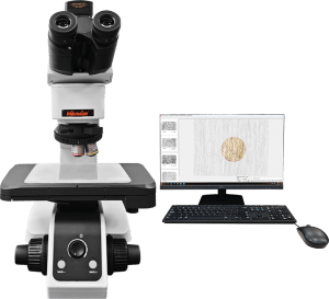
A metallurgical microscope is core lab equipment for metallographic analysis, widely adopted to inspect metal microstructure, grain boundaries, inclusions and material defects. Proper setup and operation directly determine imaging quality and the reliability of material evaluation results. Below we break down proven practical skills for daily laboratory operations.
1. Installation Environment Requirements for Metallurgical Microscopes
Place your metallurgical microscope inside a dry, well-ventilated, dust-free, vibration-isolated and corrosion-free laboratory room. Set the instrument on a level table or stable base; a vibration-damping mount is highly recommended to minimise image shake during observation.
2. Common Illumination Modes for Metallographic Observation
Main illumination options include bright-field, dark-field, polarised-light and differential interference contrast (DIC). As a general workflow rule: survey the full specimen overview under low magnification first, then switch to higher magnifications aligned with your testing goals.
- Bright-field illumination: The most frequently used mode for routine microstructure inspection and general metallographic screening.
- Dark-field illumination: Delivers superior image contrast. Ideal for identifying grain boundaries, material flaws and non-metallic inclusions within metallic specimens.
- Polarised-light illumination: Suited for phase identification in multi-phase alloys. It performs excellently for microstructural observation of anisotropic materials, as well as displaying inclusion boundaries, grain boundaries and twin boundaries.
- Differential Interference Contrast (DIC): By adjusting the DIC prism, operators can generate colour-tinted views, boost visual contrast, and reveal height variations across the specimen surface. This grants images a realistic three-dimensional relief effect.
-199x300.jpg "Master-Pro Tips for Operating a Metallurgical Microscope in Metallographic Analysis 3")
-300x289.jpg "Master-Pro Tips for Operating a Metallurgical Microscope in Metallographic Analysis 4")
3. Objective Lens Selection & Magnification Calculation
Total system magnification equals the product of objective lens magnification multiplied by eyepiece magnification. Pick matching objective and eyepiece combinations to reach your target viewing magnification.
4. Aperture Diaphragm vs Field Diaphragm Adjustment
Two key adjustable diaphragms are fitted on most metallurgical microscopes: the aperture diaphragm and the field diaphragm.
- The aperture diaphragm controls incident beam size and light intensity in the optical path. Its opening size heavily impacts overall image quality. Narrowing the aperture diaphragm sharpens images yet sacrifices optical resolution.
- The field diaphragm has no influence on microscope resolution. It limits the size of your observable field-of-view, suppresses stray light and internal tube reflections, and optimises final imaging quality.
5. Optical Filter Application
Optical filters help select specific wavelengths of incident light. Yellow-green filters are the popular choice; they absorb unwanted spectral components and yield crisp metallographic micrographs.
-300x225.jpg "Master-Pro Tips for Operating a Metallurgical Microscope in Metallographic Analysis 5")
6. Digital Image Acquisition & Scale Bar Settings
When capturing micrographs via imaging software, always embed a physical scale bar onto every metallographic picture.
The practical formula for scale-bar dimension: Total Magnification × Physical length of scale bar = 1 cm For example: – 100× magnification → 100 μm scale bar – 200× magnification → 50 μm scale bar – 500× magnification → 20 μm scale bar
7. Regular Calibration of Software Scale
Recalibrate the built-in system scale of image-analysis software on a periodic basis. A stage micrometer serves as the standard calibration reference tool.
8. Post-Processing of Captured Metallographic Images
After image acquisition, fine-tune brightness, contrast and grey-scale transformation parameters. Optimised micrographs support more accurate metallographic interpretation and defect assessment.
Conclusion
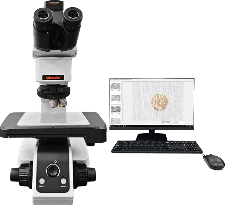
Skilled handling of a metallurgical microscope lays the groundwork for credible metallographic analysis. From lab installation, switching between bright-field / DIC illumination, tuning diaphragms and optical filters, through to scale-bar embedding and software calibration, every operational detail shapes your final micrograph quality. Laboratories in search of robust optical hardware for material characterisation often rely on equipment from Mikrosize. High-performance microscopes paired with standardised operating procedures minimise human error and deliver repeatable results for material R&D and quality-control workflows.
-150x150.jpg)