Unstable or jumping readings from ultrasonic pipe thickness gauges rank among the most frequently-reported headaches for field NDT technicians. Many operators immediately suspect defective equipment or severely aged pipework, repeatedly pressing the transducer until the screen shows a seemingly reasonable value. However, this trial-and-error approach yields unreliable inspection data. Reading stability for ultrasonic thickness measurement depends on multiple variables: material sound velocity, surface finish, couplant performance, probe perpendicularity, pipe wall curvature, and internal corrosion morphology. To resolve erratic thickness readings on industrial pipelines, technicians should look beyond screen outputs and review the complete on-site inspection workflow.
Wall-thickness inspection covers highly diverse operating scenarios. Petrochemical pipelines handle corrosive process media; natural-gas pipelines demand strict operational safety; power-plant piping runs under high-temperature conditions; municipal water pipelines often lack original construction documentation; marine piping suffers constant humidity, salt-spray corrosion and confined-space constraints. Field ultrasonic thickness testing for different pipe systems serves distinct goals: verifying compliance for new pipes, monitoring wall thinning for in-service lines, validating conditions after maintenance, and tracking expansion of localized defect zones. When readings behave abnormally, inspectors must first differentiate problems caused by operator error, material-related factors, or inherent complex defects within test locations.
Issue 1: Incorrect Material Sound-Velocity Configuration
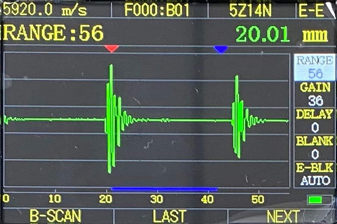
An ultrasonic thickness gauge does not “see” wall thickness directly. It calculates wall thickness mathematically based on ultrasonic wave travel time and pre-set material sound velocity. Carbon steel, stainless steel, aluminum, copper and plastic all feature unique acoustic velocity values. Even if displayed figures stay steady, wrong velocity parameters generate systematically inaccurate measurement results.
Common field pitfalls occur when pipe nameplates are missing, or sections of carbon-steel piping get replaced with stainless-steel segments during overhaul. Mixed metallic and non-metallic pipe sections within one system also create risks. Reusing one fixed sound-velocity setting across dissimilar materials produces consistent-looking yet incomparable datasets.
Best-practice workflow: Confirm base material grade before inputting corresponding sound-velocity values. For critical piping circuits, perform verification against reference calibration blocks of identical material with known wall thickness. Document material-judgement rationale for legacy pipes with unknown material specifications. Keep sound-velocity parameters unchanged during repeat inspections; otherwise thickness changes cannot be reliably distinguished from parameter-induced deviations.
Issue 2: Inadequate Surface Preparation on Pipe Outer Surfaces
Oil stains, loose rust, dust, peeling paint and flaky coating on pipe outer walls create unstable contact between transducer and base metal. Couplant gel cannot fill large surface voids; ultrasonic signals either fail to penetrate the workpiece or return chaotic reflected echoes, leading to jumping ultrasonic thickness gauge readings. Many field teams skip thorough cleaning and only wipe surfaces with rags, generating inconsistent values even at identical measuring points. For corroded pipes, remove loose surface layers at test spots to achieve stable transducer contact.
Surface pre-treatment must comply with site safety and process specifications. Avoid arbitrary grinding or hot-work operations on pressurized, high-temperature or flammable-medium pipelines. Follow official maintenance procedures for pipes protected by anti-corrosion coatings or thermal insulation. Successful coupling for ultrasonic pipe thickness inspection relies on proper preparation under permitted operating conditions rather than excessive manual pressing force.
Observed Phenomenon Root Cause Recommended Countermeasures
Readings swing sharply up and down Poor acoustic coupling, tilted probe angle Re-prepare contact surface, replenish couplant gel, maintain strictly perpendicular probe placement
Multiple measurement points deviate consistently from design wall thickness Mismatched material sound-velocity setting Cross-check pipe material grade; validate readings with calibrated reference test blocks
Isolated local readings show unexpectedly thin wall values Internal erosion, pitting corrosion or localized material loss Expand measurement coverage on surrounding areas; log locations showing minimum wall thickness
Poor repeatability on small-diameter pipe sections Insufficient contact area on curved surfaces Deploy curvature-matched transducer; optimize measuring-point orientation
| Observed Phenomenon | Root Cause | Recommended Countermeasures |
| Readings swing sharply up and down | Poor acoustic coupling, tilted probe angle | Re-prepare contact surface, replenish couplant gel, maintain strictly perpendicular probe placement |
| Multiple measurement points deviate consistently from design wall thickness | Mismatched material sound-velocity setting | Cross-check pipe material grade; validate readings with calibrated reference test blocks |
| Isolated local readings show unexpectedly thin wall values | Internal erosion, pitting corrosion or localized material loss | Expand measurement coverage on surrounding areas; log locations showing minimum wall thickness |
| Poor repeatability on small-diameter pipe sections | Insufficient contact area on curved surfaces | Deploy curvature-matched transducer; optimize measuring-point orientation |
Issue 3: Poorly-Planned Measurement-Point Layout
Pipe-wall thinning normally follows distinct spatial patterns. Higher risk areas include outer arcs of pipe elbows, tee-junction merging zones, reducer transitions, upstream & downstream of valves, pump discharge outlets, pipe low-points and support contact regions. These positions suffer far higher erosion-corrosion risk compared with straight pipe segments.
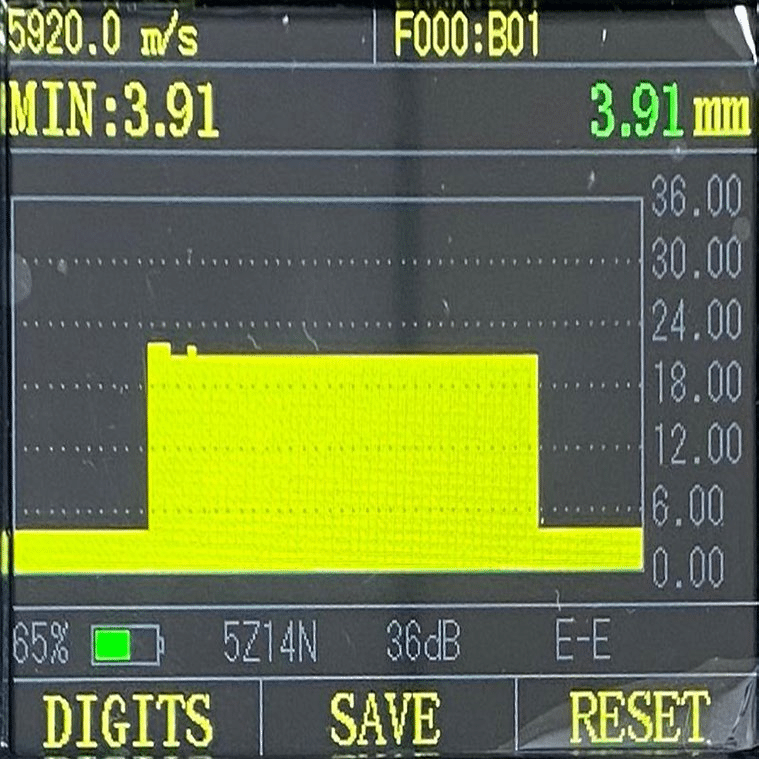
If inspectors select measurement points only based on easy physical access, readings may appear stable yet completely miss high-risk defect zones. The objective of ultrasonic pipe thickness survey is not confirming good-condition spots, but identifying minimum-wall-thickness locations and monitoring potential defect propagation trends.
Industry-standard procedure: Take multi-point readings circumferentially and axially. Record data in top-bottom-left-right or finer angular divisions around pipe circumference; space measuring locations along pipeline running direction. When abnormally thin wall values appear, extend testing to adjacent circumferential and axial zones. For priority-critical piping, mark test locations on isometric drawings to guarantee accurate re-location during future periodic inspections.
Issue 4: Avoid Over-Interpreting Raw Gauge Readings as Final Engineering Conclusions
Hand-held ultrasonic thickness gauges deliver practical on-site non-destructive wall-thickness screening, yet cannot fully replace formal standardised inspection reports or safety-assessment judgements. A low thickness reading only flags a spot requiring close attention. Decisions regarding depressurised operation, local patching, pipe replacement or expanded inspection scope require comprehensive evaluation referencing design wall thickness, corrosion allowance, conveyed-medium properties, working pressure-temperature parameters, pipe class and applicable NDT regulatory requirements.
Conversely, normal-looking readings never guarantee full pipeline integrity, as untested sections may contain hidden localized defects. Pipe thickness inspection integrates material science, instrument performance, field-operation discipline and quality-management protocols. When encountering unstable outputs, perform systematic troubleshooting across sound-velocity parameters, surface preparation, coupling quality, probe angle, point-distribution strategy and expanded re-measurement, which proves far more efficient than repeated blind testing.
Conclusion
To sum up, jumping or unstable ultrasonic pipe thickness gauge measurements seldom stem purely from faulty hardware. Common triggers cover incorrect sound-velocity setup, insufficient surface cleaning and poor couplant contact, improper probe angle, unreasonable measuring-point selection and unrecognised internal pitting-corrosion morphology. Field technicians should follow structured troubleshooting workflows rather than relying on random repeated measurements. Raw instrument readings serve only as screening data; final safety evaluation of industrial piping must combine design documentation, process parameters and full-scope inspection evidence.
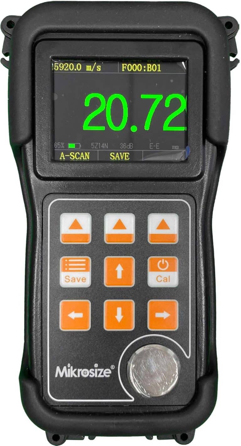
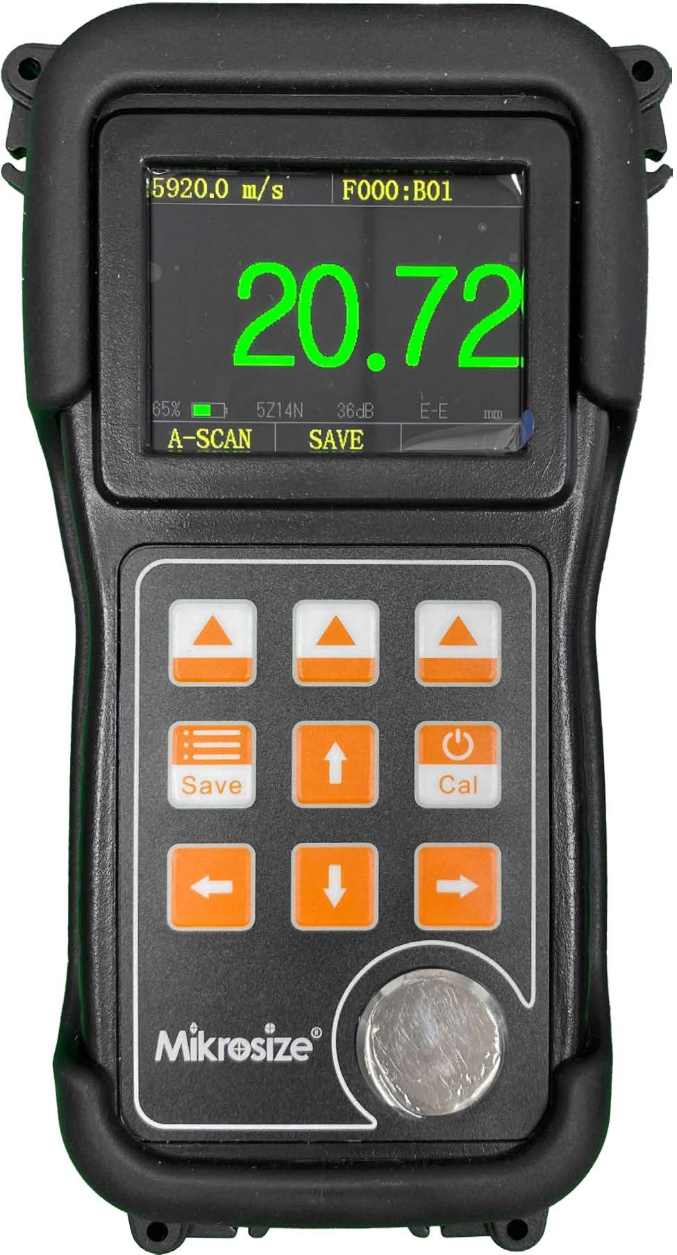
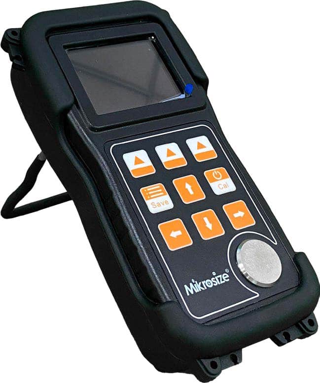
If you seek reliable inspection hardware and technical guidance for in-service pipeline ultrasonic thickness testing, Mikrosize provides complete NDT measurement solutions for petrochemical, power-generation, marine and municipal piping systems. Mikrosize’s ultrasonic thickness gauges support flexible sound-velocity adjustment, high-noise-rejection signal processing and diverse transducer options for curved and corroded pipe surfaces, helping field inspectors capture stable, repeatable wall-thickness datasets and streamline your whole pipeline-maintenance inspection workflow.