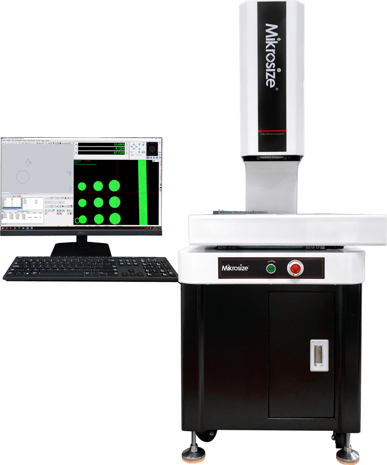
Vision measuring machine (VMM), also known as video measuring system or optical coordinate measuring machine, is a non-contact precision metrology instrument widely used for inspecting part dimensions, geometric shapes and positional tolerances across modern manufacturing industries. Many quality engineers and procurement staff often raise questions about how vision measuring machines operate, core hardware modules, real-world industry use-cases, and critical factors for purchasing. This blog answers these high-frequency questions to help you make better decisions for your quality-control workflow.
How Does a Vision Measuring Machine Work?
A vision measuring machine generates optical images capturing workpiece contours and surface features via its optical imaging unit. A CCD or CMOS industrial camera converts optical images into digital signals and transmits data to metrology software installed on the connected computer.
Powered by built-in measurement algorithms and calibrated reference standards, the software executes edge detection, analyzes imported digital images and outputs comprehensive measurement results. Measurable parameters cover linear dimensions including length, width and diameter, form errors such as roundness and straightness, as well as positional data like center-to-center distance between holes.
For instance, when inspecting mechanical components, operators place samples onto the machine worktable. Adjustable lighting delivers clear contours within the lens field-of-view. After the camera acquires images, software automatically identifies workpiece edges and calculates all target dimensional values for quality validation.
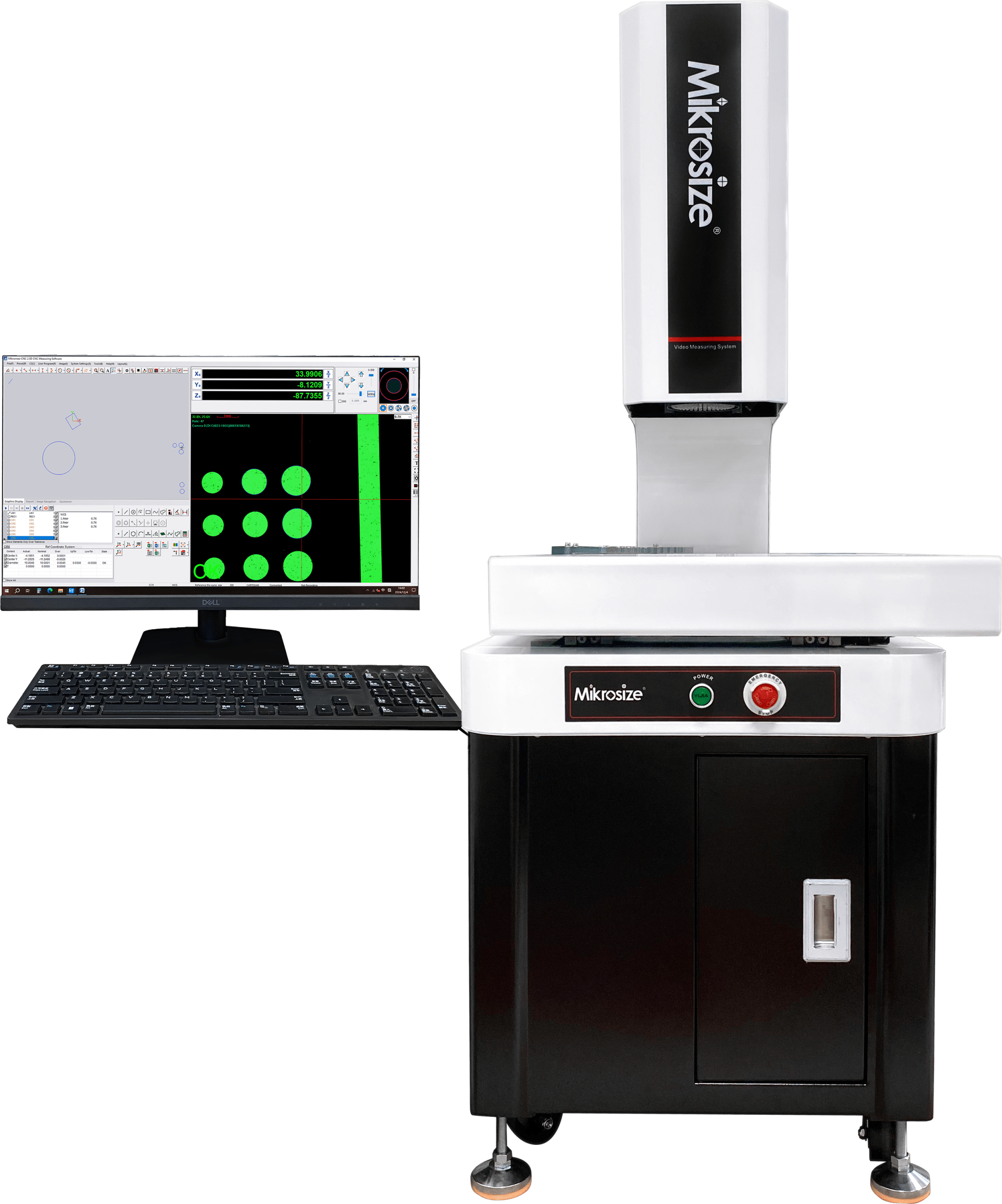
Main Core Components of Video Measuring Machine
Four major assemblies constitute a complete functional vision measuring system. Every module directly influences final measuring accuracy and operating stability.
1. Optical System
This assembly includes objective lenses and programmable light sources. Lens quality determines imaging sharpness and overall measurement precision; interchangeable zoom lenses with different magnification levels satisfy diverse accuracy-grade inspection assignments.
Common light sources contain ring light and backlight. Ring-shaped illumination highlights surface contours and surface details for opaque workpieces. Backlight is preferred for transparent or semi-transparent samples such as glass parts and thin sheets, delivering sharp outer-edge silhouettes for profile measurement.
2. Mechanical Structure
The high-precision worktable carries test specimens. It supports motor-driven precise movement along the X-axis and Y-axis directions. High-end models add motorized Z-axis travel to realize basic 2.5-D or partial 3-dimensional measurement functions. Rigid mechanical frames suppress vibration and minimize systematic measuring errors, which is critical for stable long-term metrology performance.
3. Image Acquisition Unit
Equipped with CCD camera or CMOS camera. CCD sensors feature high signal sensitivity and low image noise to produce premium-quality pictures. CMOS cameras provide high integration level and cost advantages. Their core function is transforming optical visuals into digital image data for subsequent computer-based processing.
4. Computer-Controlled Metrology Software
Regarded as the “brain” of CNC vision measuring machine. This software not only governs hardware actions including light-source brightness adjustment and worktable motion, but also undertakes image processing and geometric computation. It integrates practical measurement tools such as virtual calipers for linear distance testing and circle tools for diameter & center coordinate calculation. Besides measurement execution, the software can export standardized inspection reports storing full sets of measured data and inspection outcomes for quality traceability.


Typical Application Fields for Vision Measuring Equipment
Vision measuring machines serve as essential quality-control tools across multiple high-precision manufacturing sectors.
1. Mechanical Manufacturing Industry
In mechanical-part production workflows, these instruments verify dimensional compliance of machined components. Typical tasks cover diameter and length inspection of shaft-type workpieces, plus dimension and position accuracy validation of machined holes. In automobile component manufacturing, engineers deploy vision measuring systems to check piston, crankshaft and other engine-part features, ensuring components satisfy design specifications and guarantee vehicle engine reliability and performance.
2. Electronics Industry
For electronic component quality assurance, non-contact vision measurement delivers huge value. Operators measure printed circuit board (PCB) trace width, solder pad dimension and chip packaging outlines. When inspecting micro semiconductor devices, vision machines capture tiny lead-pin pitch dimensions. Early detection of micro-size deviations prevents defective electronic finished goods caused by component dimensional faults.
3. Mold-Making Industry
Mold factories apply vision measuring machines for design verification and finished-product quality auditing. During mold-design validation phases, technicians measure mold-cavity geometry and compare real-world readings against CAD design models to spot potential design defects ahead of mass production. After mold fabrication is finished, the equipment checks surface profile accuracy and contour tolerances. Since mold quality directly decides final injection-molding or stamping-product quality, precise mold inspection greatly lowers production reject rates.

How to Choose the Best-fit Vision Measuring Machine for Your Workshop
Before purchasing optical vision measuring equipment, evaluate four decisive factors matching your real-world inspection requirements.
1. Required Measurement Accuracy
Match machine accuracy grade with your metrology-task tolerance specifications. High-precision mechanical-part inspection demands micron-level or superior measuring performance. Generally speaking, higher measuring accuracy corresponds to higher equipment investment cost. For aerospace component inspection, users often select premium-grade vision machines with measurement uncertainty controlled within ±1 μm.
2. Measurement Travel Range
Take maximum physical dimensions of your regular workpieces into consideration. Large mechanical assemblies call for machines with spacious worktables and extended X-Y travel. For example, inspecting automotive body panel parts requires adequate table size and axis movement stroke to fully accommodate oversized samples.
3. Magnification Requirements
Different workpiece types need different optical magnification settings. Micro electronic-component inspection such as chip pin-gap measurement may need magnification ranging from 100×-200×. Routine mechanical-part dimensional checks can achieve satisfactory outcomes with 10×-50× magnification.
4. Software Functional Capabilities
Fully-featured metrology software is indispensable. Excellent software shall provide rich geometric-element measuring functions, complete GD&T form-and-position tolerance tools and intuitive human-machine interfaces. It should support fast generation of customizable inspection reports. Advanced-grade software realizes automatic part recognition and batch automated measurement, substantially lifting workshop inspection throughput.
Conclusion
Vision measuring machines / video measuring systems deliver irreplaceable non-contact dimensional-inspection capacity for modern precision manufacturing. From optical principles, mechanical build-up, cross-industry real-world applications to core purchasing criteria, understanding these fundamentals helps quality-control teams select suitable metrology hardware and streamline production-line inspection procedures.
If you are searching for reliable, cost-effective vision measuring machine solutions, Mikrosize provides comprehensive vision-metrology portfolios including manual and CNC automatic vision measuring equipment. Mikrosize’s solutions cover diverse accuracy grades, travel sizes and configurable software modules for mechanical processing, electronics and mold-making customers. Their instruments help factories achieve stable, repeatable non-contact dimensional measurement and strengthen overall production-quality management.