-e1789524591380.png "How to Choose Ultrasonic Transducers for Small-Bore Tube Thickness Testing: Fix Unstable Readings on Curved Pipe Surfaces 1")
When shopping for a small-bore tube thickness tester, many inspectors first compare host-unit resolution and measurement range, while treating transducers as an afterthought. In real-world field inspections, however, the ultrasonic transducer is frequently the core factor determining whether measurement outputs stay stable and repeatable. No matter how sophisticated your gauge mainframe is, if the transducer contact face fails to match the curved surface of pipework, technicians will have to rock the probe, apply excessive pressure or pile on coupling gel to chase valid readings. The resulting dataset cannot be trusted for acceptance inspections or corrosion-trend monitoring.
Why Standard Large-Footprint Transducers Perform Poorly on Miniature Tubing
When a flat-contact ultrasonic probe sits atop a cylindrical pipe exterior, physical contact only occurs across a narrow central strip. The smaller the pipe outer diameter, the more noticeable the air-gap hanging on both sides of the transducer. Minor shifts in inspector wrist posture can alter contact points and ultrasonic beam orientation instantly.
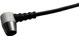
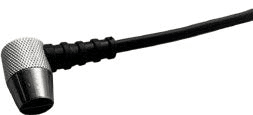
Large-area probes shine on flat components and large-size piping thanks to broad contact surfaces, yet this strength turns into a critical limitation for narrow-diameter tubing. Purpose-built small-radius tube transducers are engineered with reduced contact footprints to conform to curved surfaces — enabling reliable readings goes far beyond merely activating a “small-tube mode” in your thickness gauge software.
Five Core Criteria for Transducer Sourcing
Selection Criterion | Key Questions to Clarify | Impact on Component Selection |
Pipe Outer Dimension | What is the minimum tube OD? Do inspection scopes include elbows or tees? | Defines maximum allowable contact footprint of the transducer |
Anticipated Wall Thickness | Nominal wall thickness of new tubing; minimum residual thickness expected after corrosion loss | Dictates optimal ultrasonic frequency and measurable thickness span |
Base Material Microstructure | Carbon steel, stainless steel, alloy steel or coarse–grain cast metal | Influences sound attenuation quality and echo signal integrity |
Surface Finish Condition | Smooth bare metal, paint–coated surface, rust–covered layer, oxide scale or high–temperature operating condition | Determines coupling solution compatibility and transducer temperature rating |
Physical Access Clearance | Tube–bundle gap spacing, support brackets, leftover insulation and weld–joint obstructions | Restricts transducer housing geometry and available operating room |
Demystifying Ultrasonic Probe Frequency Selection
High-frequency transducers feature shorter sound wavelengths, boosting resolution for thin-wall sections and localized spot measurements. Nevertheless, sound signals decay rapidly inside coarse-grained, highly attenuative or thick workpieces. Low-frequency probes boast superior penetration depth but often fall short when measuring ultra-thin small-bore pipes. Therefore, the misconception that “small tubes always require the highest possible frequency” is not technically sound.
For thin-walled carbon-steel and stainless-steel capillary tubes, prioritize evaluating miniature-footprint high-frequency transducers. For coarse-grain cast components or thick workpieces with severe acoustic attenuation, opt for probes tailored to material grain characteristics. If one inspection assignment covers both thin small-bore tubes and coarse-grained thick parts, deploy multiple dedicated transducers instead of hunting for one universal all-in-one probe.
What Is the Smallest Pipe OD a Micro-Probe Can Measure?
There is no single universal outer-diameter threshold. Tubes sharing identical OD may deliver distinct echo responses due to differing wall thickness, inner-wall curvature and sound travel path. Carbon-steel versus stainless-steel tubes vary in acoustic velocity and metallurgical structure. Brand-new polished piping behaves drastically differently from in-service tubing suffering from pitting corrosion.
Published product specifications often list a minimum detectable measuring spot as well as reference tubing measurement limits under calibrated reference-block test conditions. Treat these figures only as baseline references. The gold-standard validation method remains performing practical trial tests using real-production pipe samples or equivalent-material reference blocks, assessing reading repeatability across multi-angle repositioning cycles.
Trial Validation: Do Not Judge Merely by Whether Numbers Pop Up on Screen
If your pass-fail benchmark for trial testing is “the probe shows numerical readings once placed on metal”, you risk picking unsuitable hardware. During validation work, verify at least four key performance indicators:
- Are outputs nearly identical after three consecutive re-placements on the exact same measuring spot?
- Can stable measurements be acquired at varied circumferential orientations on one pipe cross-section?
- Do usable echo signals persist at locations hitting your projected minimum residual wall thickness?
- Is excessive probe wiggling mandatory to capture valid data on moderately rough surfaces?
Your trial assessment should replicate real-world coupling agents and on-site operator hand movements. Stable lab-bench performance does not guarantee smooth operation inside dense tube banks, cramped cabin compartments or hard-to-reach equipment rear sections. Additional variables include probe cable bending constraints, transducer shell dimension and whether technicians’ fingers can maintain perpendicular probe alignment against pipe outer walls.
Identical Transducer for Straight Pipes and Elbows?
Even with matching outer diameters, straight pipe segments and elbow bends diverge in local surface curvature and physical accessibility. Elbow extrados commonly experiences manufacturing-induced wall thinning, while intrados zones suffer tight spatial confinement. Tee branch roots and reducer transition zones feature constantly shifting surface angles. While compact micro-probes improve surface conformity, they cannot ensure trouble-free readings across every complex fitting geometry.
For intricate pipe fittings, first map out zones permitting steady transducer seating, then lay out measuring points following both axial and circumferential directions. Avoid taking routine thickness readings directly over prominent weld reinforcement or heavily uneven surfaces. When weld-joint internal flaw detection is required, deploy dedicated non-destructive testing workflows for weld inspection.
Probe Selection for Coated Pipe Surfaces
Clarify your core objective first: are you measuring the base-metal wall thickness underneath surface coatings, or assessing coating layer thickness itself? These two use cases demand different gauge functionalities. Certain probes and operating modes can filter out coating interference within defined prerequisites, yet performance must be validated against reference calibration blocks of known thickness.
Bubbled coating layers, uneven paint build-up or heavily scaled surfaces will compromise reading consistency, even with coating-through measurement capability enabled. Under such circumstances, remove localized coating material on representative measuring points for cross-verification and restore anti-corrosion finishing post-inspection.
-e1789524591380-300x192.png "How to Choose Ultrasonic Transducers for Small-Bore Tube Thickness Testing: Fix Unstable Readings on Curved Pipe Surfaces 5")
-300x142.png "How to Choose Ultrasonic Transducers for Small-Bore Tube Thickness Testing: Fix Unstable Readings on Curved Pipe Surfaces 6")
Is Built-in Data Logging a Mandatory Feature?
Manual paper-based logging works fine for ad-hoc spot checks on a handful of incoming pipe pieces. For boiler tube banks, heat-exchanger bundles or marine small-bore piping field surveys, inspectors may record dozens up to hundreds of measuring points. Here, onboard data storage, statistical calculation and data-export capabilities cut down manual transcription errors. These functions only deliver value when paired with well-defined pipe identifiers and measuring-point labelling schemes on-site.
When leveraging these digital features, keep comprehensive inspection logs documenting transducer model number, sound-velocity setup, surface condition, duplicate measurement outcomes and inspection calendar dates.
Practical Transducer-Sourcing Recommendations
- Narrow down candidate probes starting from your minimum field pipe outer diameter and worst-case minimum residual wall thickness.
- Fine-tune frequency grade and probe style based on alloy composition, operating temperature and grain microstructure.
- Execute repeatability verification with authentic production samples; avoid relying solely on polished standard steel reference tubes.
- For in-service corrosion surveys, simulate rough field surfaces and confined-access working environments during pre-purchase trials.
A well-matched small-diameter tube thickness-measurement setup lets field specialists capture repeatable numerical outputs without constant probe rocking, and supports targeted re-measurement for suspicious low-thickness spots. Only after you select the correct transducer can host-gauge merits such as high baseline accuracy, statistical computation and batch-data export deliver genuine practical benefits.
Conclusion
Selecting ultrasonic transducers for small-bore tubular component inspection is far more than checking spec-sheet figures. Real-world field variables including curved pipe geometry, material grain variation, degraded surface finishes and tight access clearance heavily influence inspection reliability, repeatability and overall inspection efficiency. Many purchasing teams overemphasize main-gauge parameters while overlooking transducer performance, which frequently leads to inconsistent datasets, prolonged on-site troubleshooting and unreliable corrosion assessment outcomes.
Mikrosize delivers comprehensive ultrasonic thickness-testing hardware and tailor-made transducer portfolios built for demanding small-diameter pipe inspection scenarios. Backed by abundant field-proven experience covering heat-exchanger tubing, boiler pipe bundles and process-plant miniature pipe circuits, Mikrosize helps inspection teams match optimal probe-gauge combinations for diverse working conditions. Rather than pushing universal one-size-fits-all solutions, Mikrosize advocates real-sample pre-validation workflows, assisting end-users to acquire stable, traceable measurement data for equipment health evaluation, asset integrity management and regulatory compliance acceptance testing.
-150x150.jpg)