When shopping for a high-precision ultrasonic thickness gauge, many buyers first check resolution values such as 0.1 mm, 0.01 mm or 0.001 mm. Smaller numbers seem to promise finer measurement performance. Nevertheless, focusing solely on resolution often leads to poor purchasing decisions in real-world quality-inspection workflows. Resolution describes the smallest displayed increment of readings. It does not guarantee consistent, trustworthy measurements across different materials, workpieces or operator skill levels. Actual field performance depends heavily on material properties, thickness measurement range, probe configuration, sound velocity calibration, on-site environmental conditions and data-management capabilities.
For regular thick-wall steel plates, users should prioritize measurement range and reading stability. For thin sheets, thin-walled tubes, plastic components, glass parts, ceramic pieces and precision-machined workpieces, inspectors need to pay extra attention to effective resolution, probe contact footprint, minimum measurable spot size, sound-velocity adjustment, measurement repeatability and retesting workflows for anomalous readings. Instrument selection should never chase the most impressive-looking specification on datasheets. Instead, evaluate equipment against real-world operating conditions.
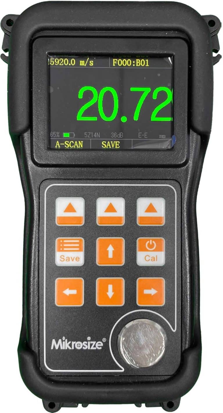
iThick-7000 Ultrasonic Thickness Gauge
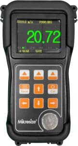
iThick-4000 Ultrasonic Thickness Gauge
-2-121x300.jpg "How to Select a High-Precision Ultrasonic Thickness Gauge: Don’t Only Look at Resolution 3")
iThick-200 Ultrasonic Thickness Gauge
-2-151x300.jpg "How to Select a High-Precision Ultrasonic Thickness Gauge: Don’t Only Look at Resolution 4")
1. Confirm your target test materials first
Ultrasonic thickness measurement relies on the material’s ability to transmit ultrasonic waves and generate identifiable back-wall echoes. Testable materials cover steel, aluminum, copper, stainless steel, glass, ceramics and various plastics. These substances differ greatly in acoustic velocity and ultrasonic attenuation. Even with a finely resolved instrument, incorrect sound-velocity settings for a given material will produce meaningless outputs.
Before purchasing, list your primary test subjects: thin-gauge metal sheets or injection-molded plastic parts? Flat panels or thin-walled tubing? Room-temperature specimens or hot post-processing components? Laboratory samples or mass-production batch-inspection parts? These practical questions matter far more than simply asking “which gauge is the most accurate”.
2. Match thickness range to workpiece geometry
Select a measurement range that aligns with your actual workpieces. Too-narrow measuring limits cannot cover thick specimens. Over-large ranges paired with unsuitable resolution and probes will fail precision thin-part testing. Thin sheets, thin-walled tubes and miniature components demand small probe contact areas. Coarse-grain castings and composite materials require strong echo-reception performance. Hot workpieces call for high-temperature-resistant probes and controlled dwell contact time.
Many purchasers overlook workpiece shape. Flat-surface testing is relatively straightforward. Thin-walled pipe inspection must account for surface curvature. Injection-molded parts feature reinforcing ribs and localized uneven surfaces. Glass testing requires clean surfaces and careful edge-zone handling. Stable probe coupling directly determines reading reliability.
|
Selection Scenario |
Key Parameters & Capabilities |
Rationale |
|
Measuring thin sheets |
Resolution, minimum measurable thickness, measurement repeatability |
Thin specimens are highly sensitive to sound–velocity drift and coupling conditions |
|
Measuring thin–walled tubes |
Probe contact footprint, curved–surface adaptability |
Unstable outer–wall coupling creates fluctuating readings |
|
Measuring plastic components |
Adjustable sound velocity, batch–specific calibration |
Plastic acoustic properties shift across grades and manufacturing processes |
|
Measuring glass & ceramic |
Echo stability, surface–preparation compatibility |
Hard brittle materials suffer reading drift from surface contamination |
|
Measuring high–temperature workpieces |
High–temperature probes, limited contact duration |
Heat alters probe performance and material sound velocity |
-1-300x191.jpg "How to Select a High-Precision Ultrasonic Thickness Gauge: Don’t Only Look at Resolution 5")
-2-300x300.jpg "How to Select a High-Precision Ultrasonic Thickness Gauge: Don’t Only Look at Resolution 6")
3. Accuracy and resolution are not identical concepts
Resolution refers to the smallest numerical change an instrument can display, for instance a 0.001 mm display step. Measurement accuracy is shaped by hardware design, calibration status, probe condition, material sound velocity, reference calibration blocks and human operation. A gauge with excellent display resolution will still deliver unstable outputs without proper sound-velocity calibration or clear material back-wall echoes.
For high-precision applications, treat resolution as a baseline requirement. Prioritize measurement repeatability and metrological traceability as core quality-control benchmarks. Key assessment questions include: Do repeated readings at one measuring point stay consistent? Do different operators yield major deviations? Do readings remain reliable after calibration against certified reference blocks? Can inspection logs record sound-velocity values, probe serial numbers and exact measurement points? These points deserve top priority for enterprise procurement.
4. Laboratory-grade versus on-site field deployment
Laboratory-based testing emphasizes reading stability, sample traceability, complete audit logs and reproducible test methodologies. Field inspection prioritizes testing speed, rugged probe durability, high-visibility displays, easy coupling application and quick re-check for abnormal measurement points. Laboratory samples often demand meticulous sound-velocity compensation and multiple replicate measurements. Production-floor equipment must deliver credible data while supporting fast batch sampling for quality-control teams.
For facilities running both laboratory and shop-floor testing, implement unified inspection protocols. Laboratories complete method validation, reference-block verification and deep-dive re-analysis of defective samples. Field units handle incoming-material checks, in-process monitoring and finished-goods spot checks. This prevents conflicting datasets between lab and production environments.
5. When multi-probe setups become necessary
A single standard probe meets requirements if you only test uniform flat metal panels. Multi-probe configurations deliver greater flexibility for mixed-specimen workflows covering thin sheets, micro-size components, plastic parts, glass, coarse-grain castings and hot components. Standard general-purpose probes suit regular flat workpieces. Miniature micro-diameter probes serve small-area test spots. Coarse-grain optimized probes handle large-grain metallic materials. High-temperature probes support measurements on heated components.
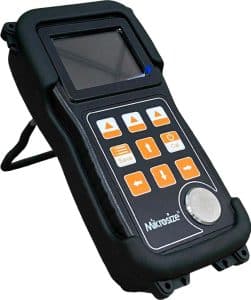
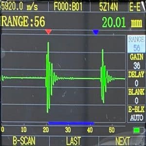
Take the Mikrosize ultrasonic thickness tester as an example. This instrument performs thickness verification on wave-permeable materials including metals, glass, ceramics and polymers. Swappable dedicated probes adapt it to diverse workpiece geometries. It represents a practical multi-material solution for industrial on-site quality assurance. Even so, users must match sound-velocity settings, probe selection and internal quality-control standards to their unique test objects.
6. Conduct sample validation before final procurement
If you work with unfamiliar specimen types, run practical validation with representative production samples. Verify these performance indicators: stable reading acquisition; acceptable fluctuation for repeated measurements at identical points; logical measurement variation matching material and manufacturing characteristics; sound-velocity recalibration via traceable reference foils; secure probe surface coupling; and low operator learning barriers.
High-precision ultrasonic thickness gauges do not automatically improve with more feature sets or ultra-fine display digits. Follow this logical selection workflow: define material and workpiece geometry, confirm applicable thickness range, select matched probes, validate sound-velocity parameters and measurement repeatability, and integrate data logging, re-testing rules and record retention into formal quality-control procedures. Equipment chosen using this structured approach delivers dependable long-term performance for manufacturing quality assurance and laboratory analysis.
Conclusion
Choosing the right ultrasonic thickness measuring instrument is never about chasing the highest-looking numbers on specification sheets. Users must match hardware capabilities to real-world variables: material acoustic traits, part geometry, operating temperature and existing quality-management workflows. Reliable thickness inspection balances proper probe matching, sound-velocity tuning and consistent operator practices rather than relying purely on nominal display resolution. Mikrosize supplies a comprehensive series of ultrasonic thickness-measurement solutions, covering multiple probes, calibration accessories and field-ready instruments to support quality-control teams across metalworking, plastics processing, glass-ceramic manufacturing and general precision-component industries. By pairing suitable Mikrosize hardware with standardized test protocols, enterprises can achieve stable, traceable thickness measurement results for both laboratory research and mass-production shop-floor environments.
-150x150.jpg)