
Cracks represent critical failure signatures of engineering materials. Observing and characterizing cracks is essential for determining failure mechanisms, executing quality control, and optimizing manufacturing processes. A metallographic microscope serves as the core instrument for imaging surface and near-surface crack morphology, propagation paths, and interactions with surrounding microstructures. This article outlines a complete workflow for crack observation and analysis using the Mikrosize iMetal-850 R/TR Upright Metallographic Microscope, covering specimen preparation, observation-mode selection, feature measurement, and root-cause deduction, delivering standardized, actionable operational procedures for industrial and laboratory users.
Part 1: Core Challenges and Instrument Requirements for Crack Observation
1.1 Unique Difficulties in Crack Analysis
Conventional metallographic microstructure observation differs significantly from crack evaluation, which presents notable challenges:
- Difficult identification: Micro-scale narrow crack openings can easily be confused with scratches or impurity lines.
- High integrity requirements: Analysts must fully capture crack initiation sites, propagation trajectories, and tip morphology. Artifacts introduced during specimen preparation will directly produce misinterpretation.
- 3-dimensional information demand: Cracks possess depth and directional features; 2-dimensional surface views alone cannot supply complete diagnostic information.
1.2 Key Instrument Configuration of Mikrosize iMetal-850 R/TR
To overcome the above-mentioned obstacles, the Mikrosize iMetal-850 R/TR Upright Metallographic Microscope integrates premium hardware specifications:
- Intelligent light-intensity management system: Automatically adjusts brightness during objective-lens switching, eliminating dim-image defects common on traditional microscopes at high magnification and delivering consistently sharp imaging.
- High-power 4500 K LED light source (CRI ≥95, 50 000-hour service life, low heat output). Its brightness matches a 100 W halogen lamp and supports multi-scene illumination.
- Beam-splitting prism assisted focusing (FA) system plus full-field Köhler illumination. Inner-wall light-absorbing coating suppresses stray light and enables high-contrast, uniform metallographic imaging.
- Motorized encoded objective turret with hardware-software integration: Embeds metadata parameters into captured images. This reduces setup errors, cuts operating time and boosts inspection throughput.
- Standard 5X-50X long-working-distance plan semi-apochromatic objectives, compatible for brightfield and darkfield. The optional 100X dry objective achieves 390 nm resolution and supports brightfield, darkfield, and polarizing observation modes.
- Coaxial coarse-fine focusing combined with large-travel double-layer mechanical stage. It supports convenient manipulation for specimens of varied dimensions and satisfies high-precision requirements for research-grade and industrial metallographic analysis.


Product Applications of Mikrosize iMetal-850 R/TR:
- Metallographic analysis of metallic materials: Visualize microstructures to support material-property assessment and quality inspection.
- Ore petrographic analysis via polarizing observation: Accurately identify mineral types and structures for geological-research datasets.
- Electronic-component inspection: Characterize internal structures and solder-joint conditions to guarantee electronic-device manufacturing quality.
- Polymer-material research: Evaluate micro-morphology and microstructure to accelerate formulation tuning and R&D progress.
- Industrial quality-control workflows: Rapidly detect surface defects and micro-flaws to elevate production management standards.
- Scientific-research laboratories: Deliver multi-mode micro-observation for diverse materials-science experiments and analyses.


Part 2: Specimen Preparation — The Decisive Initial Step
Improper specimen preparation can generate artificial false cracks or conceal genuine crack features.
2.1 Sampling and Mounting
- Sampling location: Specimens must contain crack initiation zone, propagation zone and crack tip region.
- Mounting protection: Vacuum-impregnation cold mounting is mandatory for open cracks or fragile samples. Inject low-viscosity epoxy resin under vacuum into crack cavities. After curing, the resin provides mechanical support and prevents crack widening or contamination in subsequent grinding steps.
- Mounting-material suggestion: Adopt transparent or semi-transparent cold-mounting compounds to facilitate lateral inspection.
2.2 Grinding and Polishing
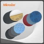
The objective is to remove the deformed surface layer and reveal authentic crack openings, without rounding crack edges or removing internal corrosion debris. Recommended workflow:
- Prefer gentle manual grinding over automatic grinders. Frequently verify specimen status under low magnification of the Mikrosize iMetal-850 R/TR.
- Progress sequentially through finer metallographic abrasive papers. Align grinding direction perpendicular to crack-propagation orientation to preserve crack opening geometry.
- Keep polishing duration short. Utilize short-nap polishing cloth paired with diamond-suspension polishing agent.
- Critical post-polishing step: Perform mild chemical etching. Light etching enhances contrast between cracks and matrix microstructures; excessive etching will destroy fine morphological details.
2.3 Preservation and Enhancement Techniques for Crack Features
- For cracks filled with oxidation/corrosion products: Minimize polishing or apply only light polishing, so corrosion-product residues are retained for subsequent EDS compositional analysis.
- For tightly closed microcracks: Implement cathode vacuum sputter-coating after polishing. An ultra-thin metallic film becomes discontinuous across crack gaps, improving crack detectability under darkfield illumination.
Part 3: Systematic Microscope Observation Workflow
3.1 Survey from Macro-scale down to Micro-scale
- Low-magnification scanning (5X-20X): Use wide-field low-power objectives on the Mikrosize iMetal-850 R/TR to map overall crack distribution and trajectories. Capture panoramic low-magnification images and mark crack positions.
- Intermediate-magnification brightfield observation (50X-200X): Document crack geometry: straight, curved, branched, or network-shaped. Make preliminary judgments regarding crack-microstructure interactions: intergranular propagation versus transgranular propagation.
3.2 Application of Core Contrast Modes
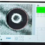
- Darkfield observation (primary diagnostic technique) Switch the microscope to darkfield illumination. Cracks, voids, and non-metallic inclusions scatter incident light and appear as bright lines or spots against a dark background. Darkfield excels at identifying subtle microcracks and secondary branches, judging crack penetration status, and measuring opening width.
- Polarizing observation (auxiliary evaluation) For materials such as titanium alloys and zirconium alloys, polarizing modes visualize grain-orientation alterations adjacent to cracks and help locate stress-concentrated zones.
3.4 High-magnification targeted inspection (500X-1000X)
Leverage high-resolution objectives to examine key crack features:
- Crack origin: Search for initiation sources including inclusions, voids, machining tool marks, and surface defects.
- Propagation paths:
Intergranular crack: Extends along grain boundaries, displaying honeycomb or network morphology, frequently linked with corrosion, overheating, or stress-corrosion cracking.
Transgranular crack: Traverses grain interiors with relatively straight paths, typically associated with fatigue or overload failure.
Mixed-mode crack: Combines intergranular and transgranular characteristics.
- Crack-tip morphology:
Sharp tip: Indicates high material brittleness or unobstructed crack advancement.
Blunted tip: Plastic-deformation zone forms near the tip, signifying adequate material toughness.
- Secondary cracks and branching: Secondary micro-cracks surrounding the primary crack deliver vital clues for reconstructing stress states and failure modes.
Part 4: Crack Measurement and Quantitative Analysis
4.1 Basic Dimensional Measurements
- Crack length and opening width: Apply digital micrometer functions built within the imaging software. Curve-measurement tools are available for irregular curved cracks.
- Approximate crack-depth estimation:
- Tilted-specimen technique: Place the sample on a tilted stage of Mikrosize iMetal-850 R/TR, tilt by known angle θ, measure projected crack length L’, and calculate approximate depth d ≈ L’ × sinθ.
- Focus-difference method: Read Z-axis travel displacement of the precise fine-focus knob while shifting focus from crack opening down to crack terminus; this displacement approximates crack depth.
4.2 Calculation of Crack-related Parameters
- Crack-tip opening displacement: Measure tip opening magnitude under high-magnification observation.
- Crack-area and micro-crack-density statistics: Run automated feature recognition across multiple fields of view, compute crack area fraction or micro-crack count per unit area.
4.3 Supplementary Micro-characterization
- Microhardness testing: Indent at sequential positions on both sides of cracks and beneath crack tips. Plot hardness-versus-distance curves to characterize plastic-deformation zones and work-hardening ranges.
- Microstructure and phase analysis: Determine whether crack growth preferentially follows specific phases such as ferrite-pearlite boundaries or brittle carbide networks.
Conclusion
Performing accurate metallographic crack failure analysis for industrial quality-control labs relies heavily on standardized specimen preparation workflows and versatile upright metallographic microscope hardware. Crack metallographic analysis demands rigorous specimen preparation, multi-mode optical observation, quantitative dimensional measurement, and correlative microstructural interpretation. Every procedural misstep can produce misleading conclusions on material-failure root causes. The Mikrosize iMetal-850 R/TR Upright Metallographic Microscope from Mikrosize integrates intelligent light management, premium Köhler illumination, motorized encoded nosepiece, and multi-contrast observation capabilities (brightfield, darkfield, polarizing). This comprehensive platform addresses the practical challenges encountered during crack inspection for metallic-material failure analysis, polymer-specimen evaluation, electronic-component quality auditing, and geological petrography. Whether for routine industrial QC or advanced academic material-science research, Mikrosize delivers reliable optical-microscopy solutions to help engineers and researchers decode crack-related material-failure behaviors effectively.