Manufacturing QC inspectors frequently face a tough dilemma: installed plastic pipes, sealed blow-molded containers and automotive injection housings are only accessible from the outer side, making calipers useless for wall thickness detection. This is where ultrasonic thickness gauge, the single-side non-destructive testing solution, comes into play. Yet many technicians struggle with erratic readings and doubt if a plastic ultrasonic thickness gauge can generate reliable wall thickness data. Accuracy never depends merely on stable digital display; material sound velocity, internal structure, back surface shape, probe coupling and measuring points jointly decide data validity. Without standardized test conditions, even multi-decimal readings cannot support formal quality judgment.
1. Single-Side Ultrasonic Thickness Testing Principle
The pulse-echo logic of portable thickness meter is simple: the probe transmits ultrasonic pulses into plastic, which reflect off the inner back wall and return to the transducer. Thickness is calculated by the formula: Thickness = Sound Velocity × Round-Trip Propagation Time ÷ 2. This explains systematic measurement deviation: mismatched sound velocity directly distorts all results. PP, PE, PA and ABS with different glass fiber filler ratios, crystallization levels and processing orientations carry distinct acoustic speeds, which often deviate from factory preset sound velocity values of generic testers.
Quick On-Site Validation Method
Pick a measurable position and test with both mechanical tools and the digital ultrasonic tester. Adjust sound velocity and repeat measurements on multiple thickness zones. Only when ultrasonic data consistently matches mechanical reference values can you finalize standardized inspection workflows.
2. Suitability of Different Plastic Workpieces for Ultrasonic Testing
|
Test Object |
Suitability Rating |
On-Site Operation Focus |
|
Solid plastic pipes & flat sheets |
Highly Applicable |
Ensure uniform material, parallel front/back surfaces, fixed axial & circumferential measuring points |
|
Injection molded housings & auto interior parts |
Conditionally Applicable |
Avoid ribs, bosses, sharp corners and gate residues |
|
Blow-molded bottles & packaging tanks |
Partial Applicable |
Unstable echoes at shoulders, bottom corners and parting lines; draw dedicated measuring point diagrams |
|
Glass/mineral filled modified plastic |
Requires Pre-Sample Calibration |
Fillers cause ultrasonic scattering and signal attenuation; universal sound velocity values cannot be used directly |
|
Foamed & multi-layer composite plastic |
Limited Applicability |
Internal pores and interlayer interfaces create false overlapping echoes |
3. Preset Sound Velocity Values Are Only a Reference
Built-in material sound velocity libraries simplify initial setup but cannot replace calibration with matched reference blocks, especially for modified plastic, recycled resin and cross-supplier identical-grade materials with inconsistent acoustic properties. Factories producing multiple plastic grades should make sound velocity record cards including material type, supplier, reference sample thickness, calibrated sound velocity and test temperature. Recalibration is required after formula or mold adjustments.
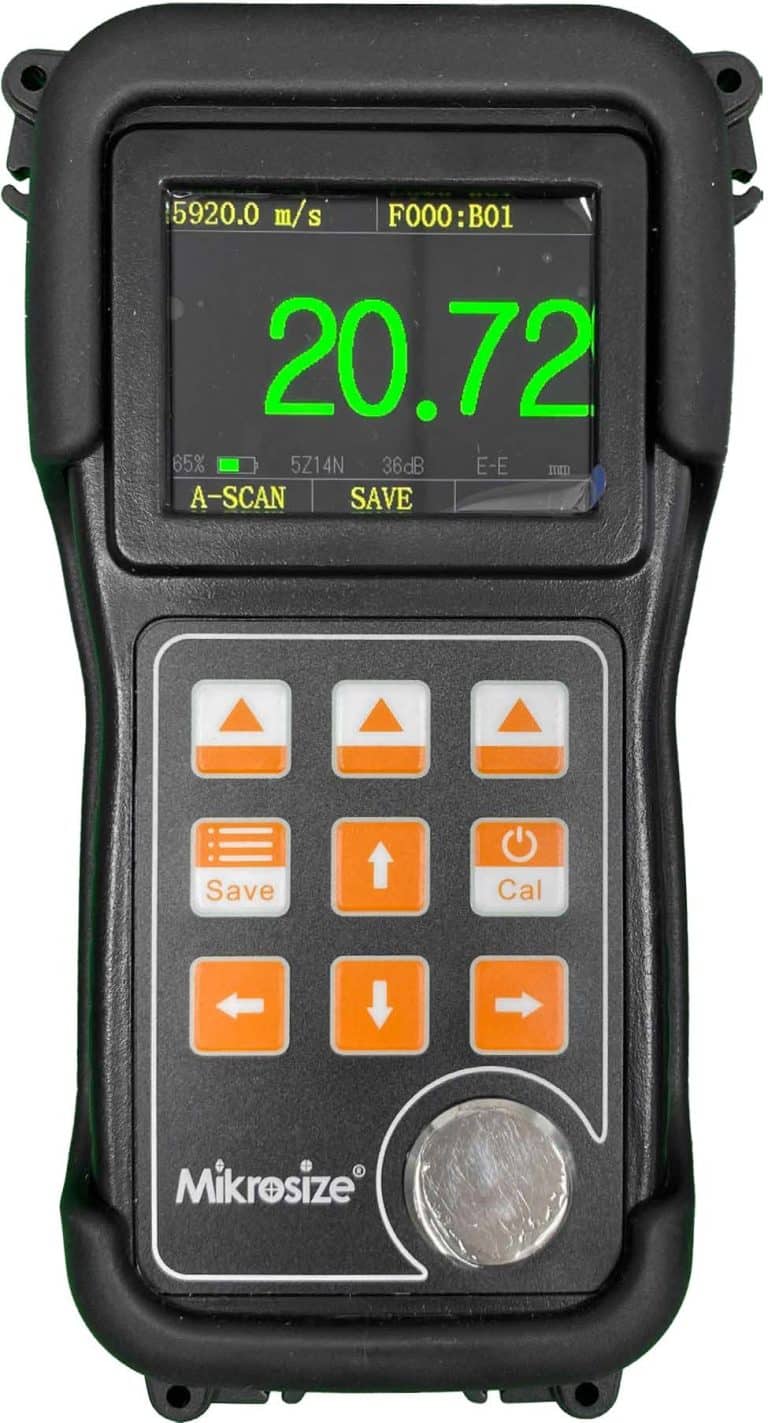
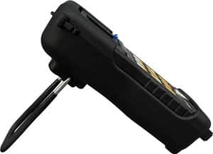
For mixed production lines switching between plastic and metal frequently, high-performance instruments cut setup time greatly. Take Mikrosize iThick-7000 Ultrasonic Thickness Gauge as an industry reference: its 1MHz–20MHz bandwidth, 72dB adjustable gain, auto E-blanking and auto-gain enable one-click sound velocity and zero calibration when switching PP, ABS, fiber-filled plastic, steel and aluminum, avoiding repeated parameter reset.
4. Curved & Thin-Wall Plastics: Primary Sources of Reading Fluctuation
Round tubes and blow-molded vessels are typical curved workpieces. Large probes only partially fit curved surfaces, leading to uneven coupling and jumping data. When measuring circular pipes, operators must fix dual-element probe direction and select mini probes matching pipe diameter.
Thin plastic parts are restricted by the probe’s near-surface blind zone. Repeated measurements are necessary to verify stability, paired with thin reference block cross-checks. For textured rough surfaces, clean testing zones and use plastic-compatible coupling fluid to prevent swelling or residue.
Premium testers solve thin and curved plastic testing pain points effectively. The Mikrosize iThick-7000 covers an effective measuring range of 0.15–3200mm (carbon steel longitudinal wave), equipped with a full range of interchangeable probes for ultra-thin packaging to thick industrial plastic tanks. Its auto ranging and data freeze functions automatically filter coupling jitter signals on curved surfaces and lock stable readings for QC recording.
5. Average Readings Easily Hide Dangerous Local Thin Zones
Plastic pipes have eccentric walls; blow-molded containers develop thin areas at shoulders and bottom corners; injection parts show uneven thickness at weld lines and turning sections. Averaging only 3–5 random points will overlook substandard ultra-thin regions.
Standardized inspection requires risk-based measuring point mapping: mark pipes by circumferential and axial serial numbers; divide bottles into mouth, shoulder, barrel and bottom zones; prioritize gates, ribs and structural turns on injection parts. Unified point serial numbers guarantee cross-batch data comparability.
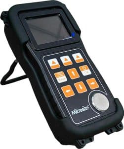
Modern testers integrate QC statistical and alarm functions to standardize batch inspection. As demonstrated by the Mikrosize iThick-7000, the independent QC mode supports pre-set upper/lower thickness tolerances based on drawings and internal standards. Out-of-tolerance values change screen color and trigger buzzer alerts; a coupling prompt shows white font with sound reminders to avoid recording invalid poor-contact data.
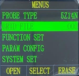
The device also satisfies full traceability requirements: it stores 520 independent files with 252 datasets each (130,000 records total), adopts grid format for quick file lookup, and comes with free Data View PC software for statistics, archiving and inspection report printing. Auto sleep, backlight adjustment and upper computer communication adapt to workshop, field and lab testing environments. Its A-scan, B-scan and multi-mode digital display plus 9 simplified operation keys enable fast parameter adjustment for mass production inspection.
6. Standardized Data Recording for Quality Management
Traceable inspection records must include product ID, plastic grade, batch number, measuring point serial number, calibrated sound velocity, probe model, workpiece temperature, operator ID and recheck results. For abnormal thin readings, re-clean the surface, reapply coupling fluid and add surrounding measuring points before slicing verification, to distinguish real thin walls from coupling interference.
|
Recording Item |
Core Quality Management Purpose |
|
Instrument serial number & measuring coordinates |
Locate identical test positions for follow-up re-inspection |
|
Material grade, nominal thickness & surface status |
Reference for sound velocity calibration and abnormal data analysis |
|
Tester model, probe & calibrated sound velocity |
Ensure consistent data comparison between batches |
|
A-scan waveform & repeated measurement results |
Confirm readings come from valid back-wall echoes |
|
Supplementary points & recheck notes |
Prevent false readings from being misjudged as quality defects |
7. Limitations of Ultrasonic Plastic Thickness Testing
Wall thickness is only one plastic quality indicator. Pipe ring stiffness, impact resistance, container sealing and weather resistance cannot be judged solely by thickness data. A standard ultrasonic thickness gauge only calculates thickness via sound wave travel time and cannot detect internal cracks, pores or delamination, which require dedicated flaw detection equipment. Test execution must comply with GB/T 11344-2021 (ultrasonic thickness measurement) and GB/T 8806-2008 (plastic pipe dimension inspection). Measuring tools, point quantity and data rounding rules follow official standards and enterprise documents.
Beyond plastic processing, the Mikrosize iThick-7000 fits multi-industry NDT work: measuring steel/aluminum panels for auto and aerospace manufacturing, testing concrete wall thickness for construction, monitoring corrosion thickness loss of pipelines and pressure vessels, and inspecting casting/welding thickness uniformity.
8. Conclusion & Troubleshooting Steps
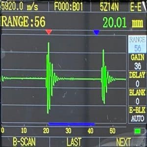
A plastic ultrasonic thickness gauge cannot deliver accurate results with one casual touch. Reliable single-side non-destructive data is only achievable with calibrated sound velocity, fixed measuring points, consistent coupling, calibrated instruments and A-scan waveform verification. It is ideal for batch sampling, production trend tracking and abnormal rechecks of plastic pipes, injection housings and blow-molded containers.
When readings fluctuate at the same point, troubleshoot in this order before averaging data:
- Recalibrate material sound velocity
- Complete probe zero calibration
- Clean workpiece surface thoroughly
- Standardize coupling fluid dosage and probe pressing posture
- Use mini probes to eliminate curved surface interference
- Verify echo authenticity via real-time A-scan waveform
For pressure vessel safety evaluation and inspection result disputes, qualified inspectors shall combine thickness data, A-scan waveforms and industry standards to issue formal conclusions. For factories with mixed plastic and metal testing needs, the Mikrosize iThick-7000 integrates complete calibration algorithms, full-series probes and end-to-end data management, serving as an all-in-one industrial thickness QC solution.
-150x150.jpg)