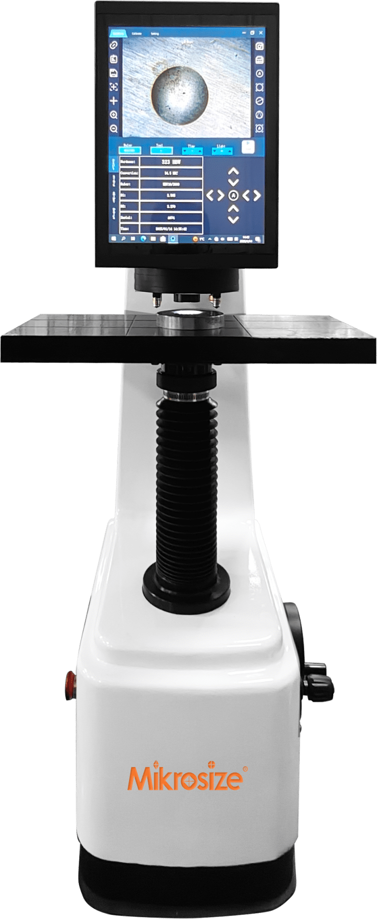
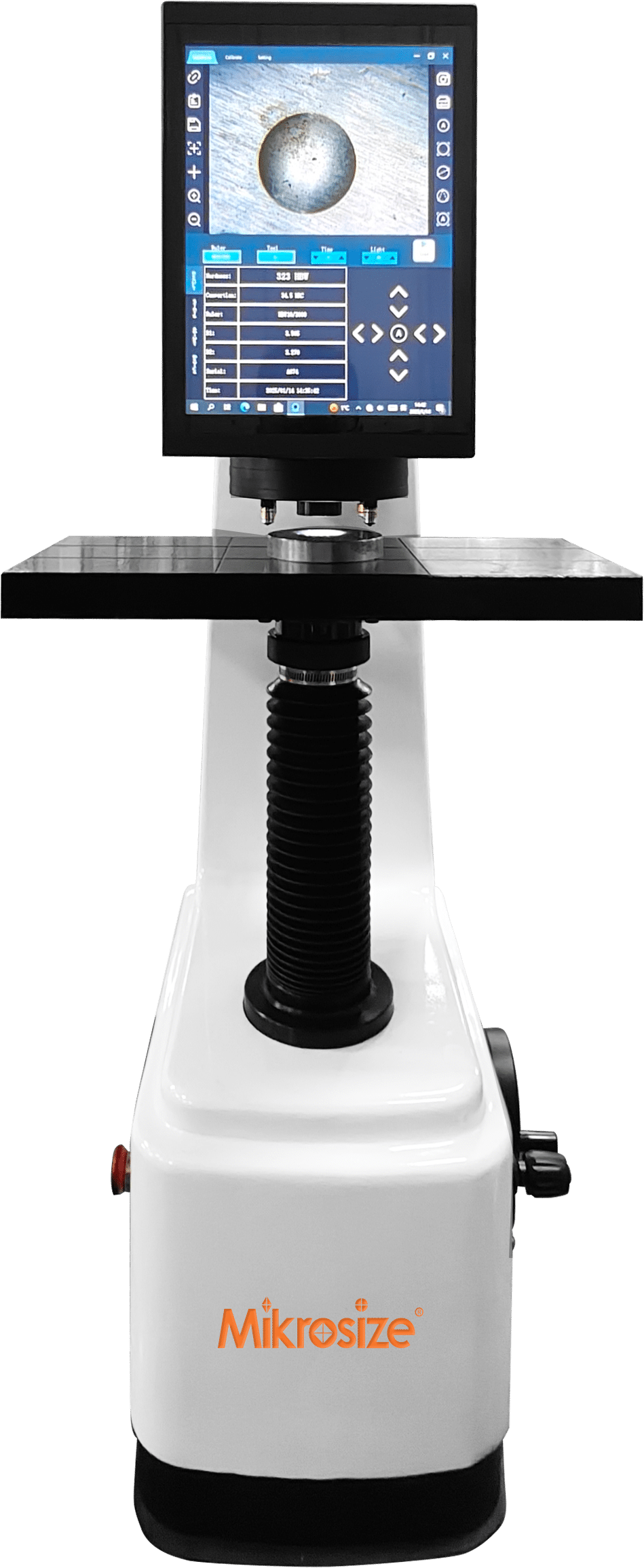
A Brinell hardness tester is widely used for hardness measurement of cast iron, carbon steel, non-ferrous metals and soft alloys across metallurgy, forging, power equipment, petroleum machinery, rail transit, automotive manufacturing and military component industries. Together with Rockwell and Vickers hardness testers, it forms the three core hardness-testing instruments for metal material laboratoriesISO.
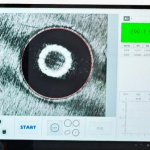
The core principle of the Brinell hardness test is to press a cemented-carbide ball indenter into the specimen surface under a defined test force. After holding the load for a specified dwell period, the applied force is removed. Operators then measure the diameter of the residual indentation on the sample surface. The spherical contact area of indentation is calculated based on the average indentation diameter and indenter ball diameter to obtain the final Brinell hardness number (HBW)Affri.
To acquire repeatable, trustworthy test results, technicians must strictly follow standardized testing specifications. Below breaks down critical operating rules for reliable Brinell hardness inspection.
1. Specimen Surface Preparation
The test surface must be flat, smooth, and free of scale, dust and oil contaminants. Surface quality directly decides whether you can capture precise indentation-diameter readings.
When preparing samples, minimize property changes caused by over-heating or excessive cold working during cutting, grinding or machining operations. Thermal damage and work-hardened surface layers will produce misleading hardness data.
2. Minimum Specimen Thickness Requirement
The specimen thickness shall be no less than 8 times the indentation depth. If visible deformation appears on the specimen backside upon completing a test, the sample is too thin for valid Brinell testing and needs replacement with thicker stock.
3. Ambient Temperature Condition
Standard tests run at room temperature ranging from 10 °C to 35 °C. For high-precision hardness evaluation with tight tolerance demands, keep testing temperature controlled at 23 ± 5 °C. Temperature drift may introduce measurable deviation in metal indentation responses.
4. Indenter Ball Selection Guidelines
Select the largest feasible ball indenter size possible, so that hardness readings represent the true mechanical property of a sufficiently large material zone. Whenever specimen geometry permits, prioritize the 10 mm diameter carbide ball, the most-common standard indenter for general-purpose Brinell hardness inspection.
5. Specimen Placement on Test Stage
Secure the specimen firmly on the tester stage. Both the specimen bottom surface and test stage surface must stay clean, without oxide scale, grease or debris. Zero specimen shifting or slipping can happen throughout the full indentation cycle. Any movement invalidates test data.
6. Test-Force Application & Dwell-Time Rules
Bring the carbide ball indenter into gentle contact against the sample surface. Apply full test force vertically without shock or vibration. The total load-ramp time from initial contact to reaching complete test force should fall between 2 s and 8 s.
Standard dwell time holding full test force lasts 10 s to 15 s. For special materials requiring extended holding periods, the allowable time error cannot exceed ±2 seconds.
7. Anti-Vibration Requirement During Testing
The entire Brinell hardness tester must remain free of external impact or vibration for the whole test cycle. Even minor shaking will distort indentation geometry and compromise measurement accuracy.
8. Minimum Spacing for Indentations
- The distance from any indentation center to the specimen edge must equal at least 2.5 times the average indentation diameter.
- The center-to-center distance between two adjacent indentations shall be no less than 3 times the average indentation diameter.
Following these spacing standards avoids material-hardening interference from neighboring impressions and edge-effect errors.
9. Indentation Diameter Measurement Method
Measure each indentation diameter along two mutually perpendicular directions. Calculate the Brinell hardness value from the arithmetic average of these two measured readings. Single-direction measurement is not acceptable for formal Brinell hardness reporting.


Conclusion
Strict adherence to standard operating procedures is fundamental for getting credible, comparable data when running Brinell hardness tests on metallic components. Every detail matters, including specimen surface finishing, sample thickness validation, temperature control, indenter selection, load timing settings and indentation spacing limits. Careless handling of these parameters will generate inconsistent hardness results and mislead material performance judgment. For labs looking for dependable hardness-testing equipment, calibration support and application guidance, partnering with reputable instrument manufacturers such as Mikrosize can help laboratories maintain high-level testing quality. By enforcing standardized workflows and choosing quality-assured hardware, material-testing facilities can reduce measurement uncertainty and improve overall lab productivity.