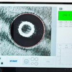
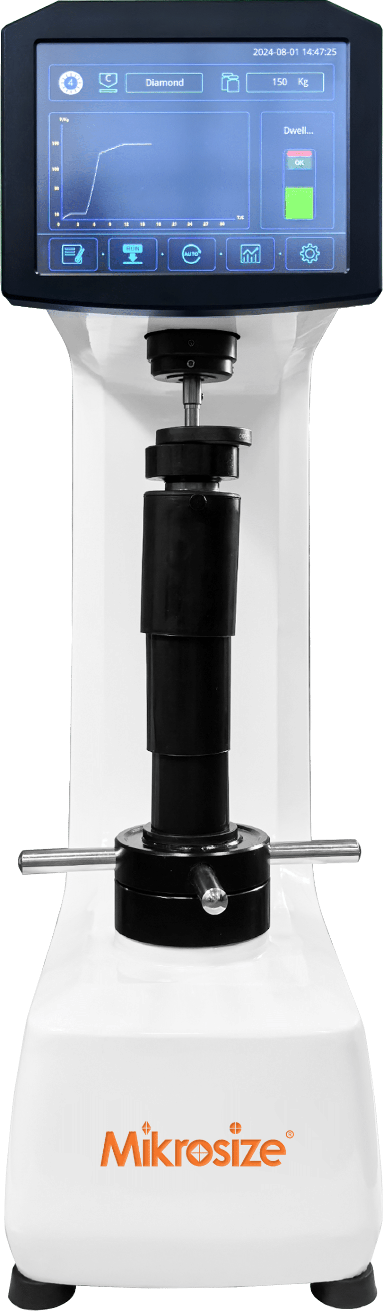
Hardness inspection of heat-treated components acts as a core checkpoint for validating heat-treatment processes and finished-part quality. Benchtop Rockwell hardness testers remain widely adopted thanks to simple workflows and broad material compatibility. Nevertheless, indentation position offset, scattered hardness readings and inconsistent indent geometry frequently compromise process tuning and batch release decisions. This blog explores actionable controls for indentation-caused measurement errors across sample surface preparation, instrument calibration, standardized operating procedures and full data traceability. It helps quality teams establish repeatable, reproducible Rockwell hardness testing workflows for production environments.
Industry Challenges & Real-World Pain Points
Within heat-treatment production, Rockwell hardness testing for quenched-and-tempered shafts, carburized-quenched components and nitrided workpieces serves both process validation and final-product acceptance. During field visits to a mechanical processing plant, one heat-treatment supervisor reported a frustrating issue: testing identical batches of quenched-and-tempered shaft parts with the same Rockwell hardness tester by different operators produced HRC deviations greater than 3 units. This large reading spread made it impossible to judge whether heat-treatment parameters met specifications.
Similar measurement inconsistencies occur more often with carburized quenched parts, nitrided components, thin-wall workpieces and parts featuring shallow effective hardened layers. Minor drift in Rockwell indentation depth control can trigger full-batch rework or scrapping.
Most measurement variability traces back to indentation-originated errors: misaligned contact between diamond indenter and workpiece surface, unstable specimen support structure, and vibration interference during force application, which shift indent positions away from target zones or distort indent shapes. Surface conditions including mill scale, decarburized layers and residual oil contamination on heat-treated parts further amplify these testing errorsNIST.
Actual Testing Requirements for Heat-Treated Specimens
Manufacturers do not merely need arbitrary hardness numbers. What QC teams truly require are repeatable Rockwell hardness readings reflecting real substrate material hardness.
- Test specimens: quenched-and-tempered parts, carburized quenched components, nitrided workpieces, induction-hardened metal parts. Critical metrics cover surface hardness, effective case depth measurement, and core substrate hardness.
- Key factors influencing judgment: indent placement (avoiding decarburized zones), indent symmetry (indicating perpendicular force loading), reading range and standard deviation (showing operator-to-operator consistency).
- Business impacts from unreliable data:
- Adjusting heat-treatment parameters such as quenching temperature and tempering holding time;
- Approving or rejecting finished production batches;
- Supporting metallurgical failure analysis — excessive indentation error makes it impossible to differentiate genuine process failure versus testing anomalies.
Technical Solutions to Minimize Rockwell Indentation Errors
Controlling Rockwell hardness indentation error for heat-treated parts covers four major phases: pre-test sample preparation, instrument health validation, standardized on-site testing operations and complete data governance.
1. Instrument Selection Guidelines
Select benchtop Rockwell hardness testers built with high-precision spindle guiding systems and stable loading mechanisms. Premium-grade equipment such as ERNST benchtop Rockwell hardness testers adopt double-cylindrical guide rail spindle assemblies to reduce side friction during loading cycles, lowering dispersion in indent-depth readings. Pair hardware with high-resolution displacement sensors (0.1 μm resolution) to capture subtle indent-depth variations accurately. Avoid over-relying on displayed digital resolution alone when selecting hardness-testing equipment.
2. Critical Sample Pre-Treatment Parameters
For heat-treated test coupons and production specimens, remove mill scale, surface decarburization layers and carbon-enriched surface zones on carburized parts. Fine grinding or polishing procedures should deliver surface roughness Ra ≤ 0.8 μm. Operators must grind with steady, moderate pressure. Over-heating during specimen grinding causes secondary tempering, which will falsify hardness test results. Clean and dry samples thoroughly after surface preparation before conducting hardness tests.
3. Calibration & Routine Performance Verification
Deploy certified Rockwell hardness reference blocks matching your workpiece hardness spectrum, for instance HRC 20-30 and HRC 50-60 grade calibration blocks. Inspect diamond cone indenters before calibration. Cracked or worn diamond indenters produce deformed indents and systematic reading bias. Industry best practice recommends running verification checks with standard reference blocks after every 200 Rockwell hardness measurements.
4. Standardized Test-Cycle Operation
Lock consistent indenter descending velocity, preload holding duration and major test-force application time. Modern Rockwell testers with embedded software enable preset loading and dwell-time parameters, eliminating human-induced timing differences that alter final indentation depth.

Step-by-Step Practical Workflow for Production QC
Step 1: Specimen Preparation
Strip surface oxide and altered layers → fine-grind to target surface roughness → clean and dry test pieces → mark valid inspection zones, keeping away from part edges, pores and carburized-layer transition boundaries.
Step 2: Instrument Calibration Workflow
Perform calibration with certified reference blocks → log calibration values. When deviation exceeds ±1 HRC, inspect diamond indenter condition or troubleshoot tester mechanics. Archive all calibration documentation for audit traceability.
Step 3: On-Site Rockwell Hardness Measurement
Secure workpieces using V-shaped anvil blocks or custom-made fixtures. Apply auxiliary supporting jigs for thin-wall components. Select appropriate test force (150 kgf for HRC scale). Execute automatic loading cycles and capture hardness outputs. Visually inspect each indent for symmetry and crack-free geometry.
Step 4: Result Validation
Take minimum three Rockwell indent readings per inspection area. Adopt the median value as representative hardness. When the reading range surpasses 1.5 HRC, re-evaluate sample surface quality or re-prepare test specimens.
Core Technical Points Explained
1. Precision control for preliminary preload and major test force
The 10 kgf preliminary preload establishes indentation starting reference points, and major force (e.g., 150 kgf for HRC) determines final indent penetration depth. Shock-type force application or delayed force unloading creates reading drift. Hardness testers equipped with closed-loop force sensors and servo-motor drive systems dynamically adjust loading curves so indent depth faithfully reflects true material hardness.
2. Spindle guiding performance and friction reduction
Radial spindle wobble creates asymmetric indent shapes. Measurement error multiplies significantly for components with shallow hardened layers. Spindle units built with double-cylindrical guide rails or cross-roller guide rails enhance loading perpendicularity and cut reading scatter.
3. Optical measurement resolution and system stability
Rockwell hardness derives from measuring indent-depth differential. 0.1 μm high-resolution depth sensors detect minor hardness gradients. This capability proves especially valuable for parts with approximately 0.5 mm thin carburized case layers when mapping hardness transition from outer surface to bulk core material.
4. Closed-loop loading mechanism benefits
Conventional lever-weight Rockwell testers suffer performance shifts caused by ambient temperature fluctuation, ground vibration and hydraulic pressure instability. Motor-driven closed-loop loading systems compensate external disturbances automatically and keep force deviation ≤ ±0.5 % of nominal test force, forming the physical foundation for stable indent-depth results.
5. Reference block management and recurring calibration
Certified hardness reference blocks carry intrinsic measurement uncertainty and gradually degrade through surface abrasion in daily use. Maintain low-, medium- and high-hardness reference-block sets covering your production hardness range. Send blocks for metrological recalibration every month and preserve calibration curves for traceability records.
6. Digital data logging and traceability software
Paper-based log sheets risk data loss and hinder trend analysis. Hardness-testing software supporting data export, hardness-gradient curve plotting and SPC statistical process control helps quality engineers spot slow hardness-value drift ahead of non-conforming production lots.
Application Boundaries of Different Rockwell Hardness-Testing Solutions
- Automatic benchtop Rockwell hardness testers: Fit for laboratory QC centers. Deliver tight indentation-error control. Ideal for thin carburized / nitrided layers and process-validation jobs requiring outstanding measurement repeatability.
- Portable Rockwell hardness testers: Suited for large-size on-site rapid screening. Constrained by specimen support, surface finish and manual-operator variability; typical reading range reaches 2-3 HRC. Not recommended for batch release decisions or metallurgical failure analysis.
- Inline automatic hardness-inspection equipment: Optimized for high-volume uniform-geometry parts such as springs and bearing races, enabling 100 % online testing. Custom fixtures are mandatory; cost barriers limit deployment for mixed-variety small-batch manufacturing.
Real-World Industry Use-Case
A commercial heat-treatment service provider accepted inspection contracts for carburized-and-quenched shaft components. Their legacy Rockwell hardness tester relied on manual force control. Variable indenter sinking speed from different operators generated large deviations in measured effective case depth, triggering repeated customer complaints.
Testing objectives: Accurately map surface-to-core hardness gradient and hold effective case-depth tolerance within ±0.1 mm.
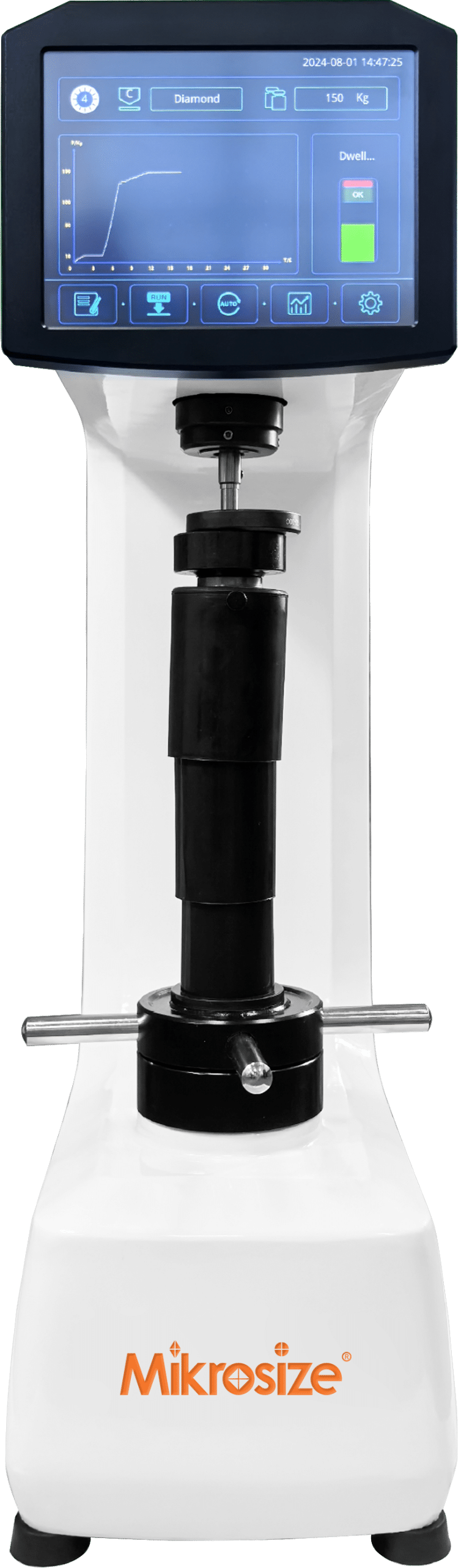
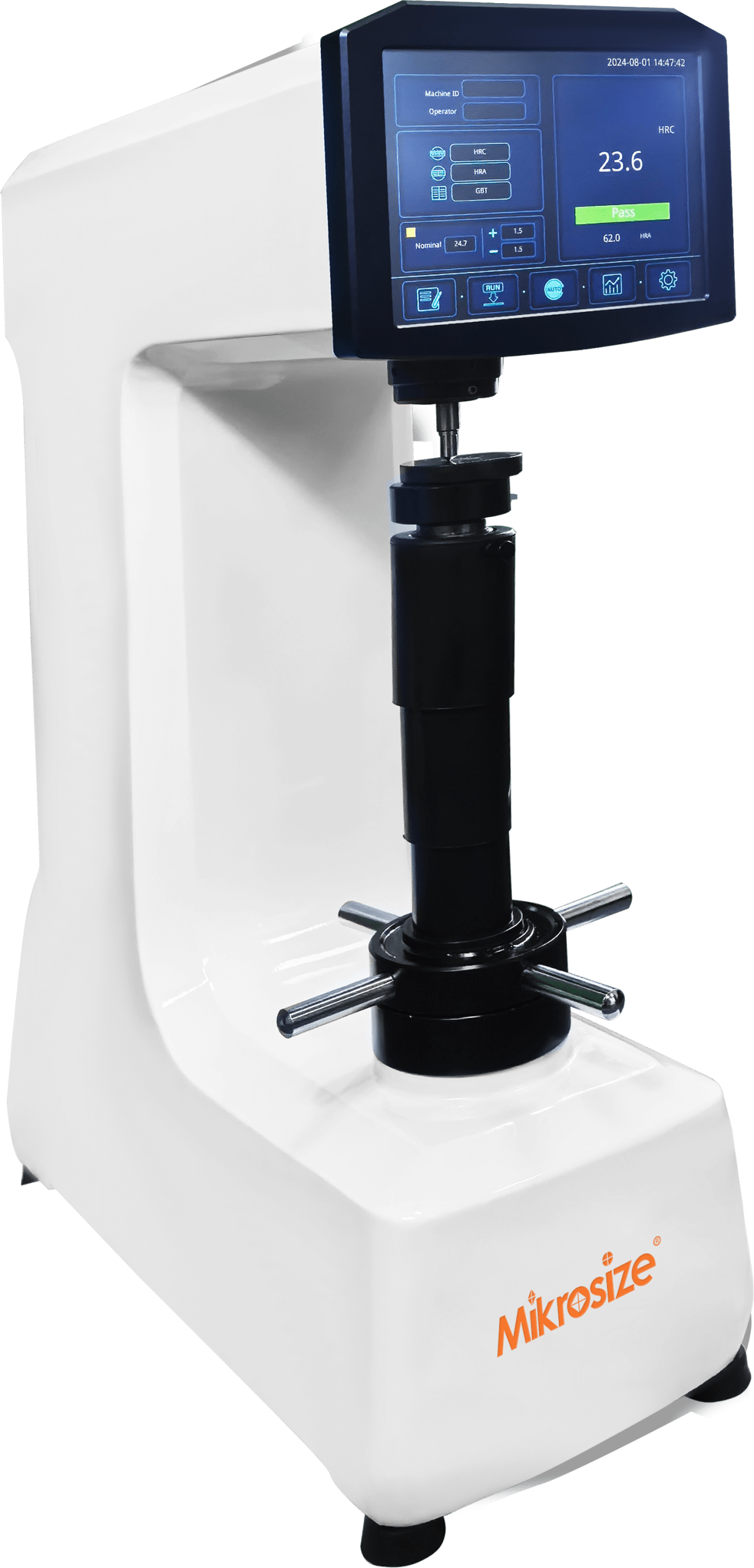
Implemented configuration: Closed-loop controlled benchtop Rockwell hardness tester, V-block fixtures and complete certified reference-block kit. Operators followed standardized SOP: sample grinding → preload application → timed force holding → unloading → hardness acquisition.
Operational outcomes: Repeatable indent positioning, measurement reading range controlled within 0.5 HRC. Consistent effective case-depth assessment eliminated batch-release disputes. Measured datasets export seamlessly to LIMS laboratory-information-management-systems for end-customer traceability.
Practical Implementation & Equipment-Selection Advice
- Clarify test-object specifications and quality thresholds first: define effective hardened-layer depth allowances and acceptable hardness variation limits, before selecting testers with matching force accuracy and measuring range.
- Conduct repeatability validation with actual production workpieces (instead of only reference blocks) during new-equipment commissioning. Evaluate how grinding methodology and fixture selection influence total measurement error.
- Build formal calibration-and-recheck workflows: perform daily calibration checks, and execute cross-comparison tests with reference blocks weekly.
- Restrict testing duties to adequately trained 1-2 dedicated QC inspectors to minimize operator-introduced variance.
- Standardize data-recording templates containing timestamp, ambient temperature, reference-block serial number and operator ID, supporting root-cause investigation for abnormal hardness readings.
- Prioritize mechanical stability over superficial display parameters. Spindle rigidity, depth-sensor resolution and closed-loop force-control architecture carry greater weight than maximum test-force rating or number of displayed decimal digits. Factor in after-sales response speed and hands-on technical training support during vendor evaluation.
Conclusion
Accurate Rockwell hardness inspection for heat-treated components depends on holistic system-level management covering specimen surface preparation, instrument mechanical performance, standardized operational protocols and full-cycle data traceability, rather than merely pursuing isolated single-point equipment precision. When you select hardness-testing hardware, focus critical evaluation on spindle guiding structure, closed-loop force-loading performance and built-in data-traceability software functions, instead of only comparing technical specifications on datasheets. Reliable hardness measurement results can only guide production-process decisions effectively once indent-originated errors are confined within process-defined tolerance windows.
If you are sourcing reliable hardness-measurement instruments for your heat-treat workshop or quality-control laboratory, Mikrosize, a global supplier specializing in material-testing equipment, delivers comprehensive Rockwell hardness-testing hardware, calibration accessories and professional technical consulting services. Mikrosize’s instruments adopt closed-loop electronic loading designs, high-precision optical sensing modules and complete data-logging functions, helping manufacturing enterprises reduce indent-related testing deviations and improve overall heat-treatment quality-control efficiency across automotive, machinery and general-metal-processing sectors.