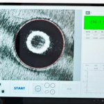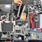
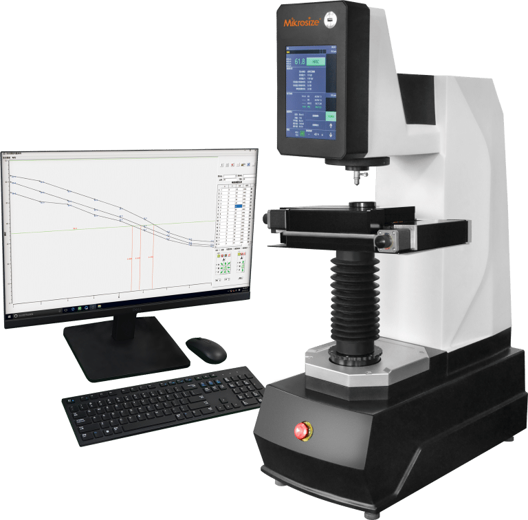
Within automotive component manufacturing, Rockwell hardness testing acts as a critical metric for evaluating heat-treatment consistency and machining quality of metal parts. Many quality-control workshops struggle with inconsistent operator techniques, poorly-managed certified reference hardness blocks, and incomplete hardness-test data traceability. This blog explores practical pain-points on production floors and builds a systematic Rockwell hardness tester calibration workflow, covering sample preparation, instrument verification, on-site inspection and digital-data archiving. This standardized procedure helps quality engineers secure repeatable test results and realize reliable cross-batch performance comparison for automotive safety-critical components.
1. Industry Background & Real-World QC Pain-Points
When auditing more than ten automotive component suppliers, one transmission-gear manufacturer uncovered a severe deviation during internal quality reviews: quenched gear samples from the same production batch delivered hardness offsets of 3-5 HRC units between day-shift and night-shift operators. Further root-cause analysis confirmed equipment itself was fault-free. The error stemmed from inconsistent understandings of zero-point calibration for Rockwell hardness testers: some technicians performed calibration before every single test run, while others only completed one calibration at the start of each working day.
This measurement inconsistency prevails widely across automotive quality labs. For engine connecting rods, wheel bearings, steering knuckles and brake discs, Rockwell test repeatability and reproducibility (Gauge R&R) directly governs heat-treatment assessment and batch release decisions. Common recurring shop-floor issues include:
- Inconsistent operator handling: variations in indenter positioning, pre-load dwell time, and load-apply / load-release speed.
- Mismanaged certified reference hardness blocks: over-utilized standard blocks with worn test surfaces continue in service without timely replacement.
- Under-estimated environmental interference: floor vibration and ambient temperature fluctuation distort hardness readings.
- Weak data traceability: heavy reliance on manual paper logs with poor correlation linking hardness values, workpiece batch codes and heat-treatment parameters.
Most workshops reduce calibration to a simple self-check routine. In reality, reliable hardness verification demands full-process control over every testing step.
2. Core Testing Requirements for Automotive Components
Automotive parts cover carbon steel, alloy steel, cast iron, aluminum alloy and powder-metallurgy materials. Valid Rockwell measurement applies for components with case-hardened or carburized layer thickness above 0.5 mm, including gear tooth surfaces, splines, bearing raceways and pin end faces.
- Primary hardness scales: HRC for heat-treated steel parts, HRB for annealed steel and copper-alloy workpieces, HRA for hard-coated cemented-carbide components.
- Production impact of test outputs: out-of-tolerance hardness triggers tempering adjustments or quenching-parameter revision. Large hardness drift signals abnormal heating curves, failed cooling medium performance or incoming-material batch variance.
Automotive QC teams do not merely pursue absolute measurement precision. The top priority is defensible, reproducible hardness test data. That means quality assurance cannot fully depend on factory-issued instrument calibration certificates alone. A closed-loop workflow must be enforced: workpiece preparation → instrument validation → on-site testing → result cross-check → data archiving → process feedback.
3. Technical Solution Framework
3.1 Equipment Selection for High-Volume Automotive QC
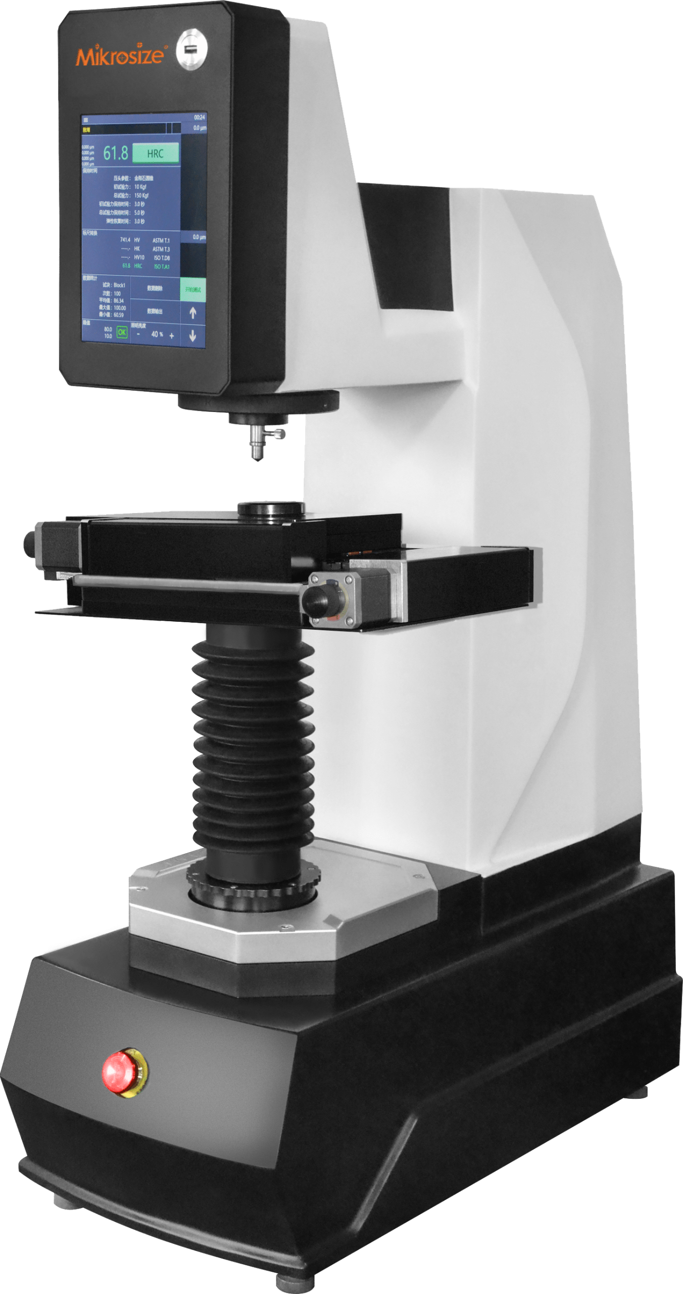
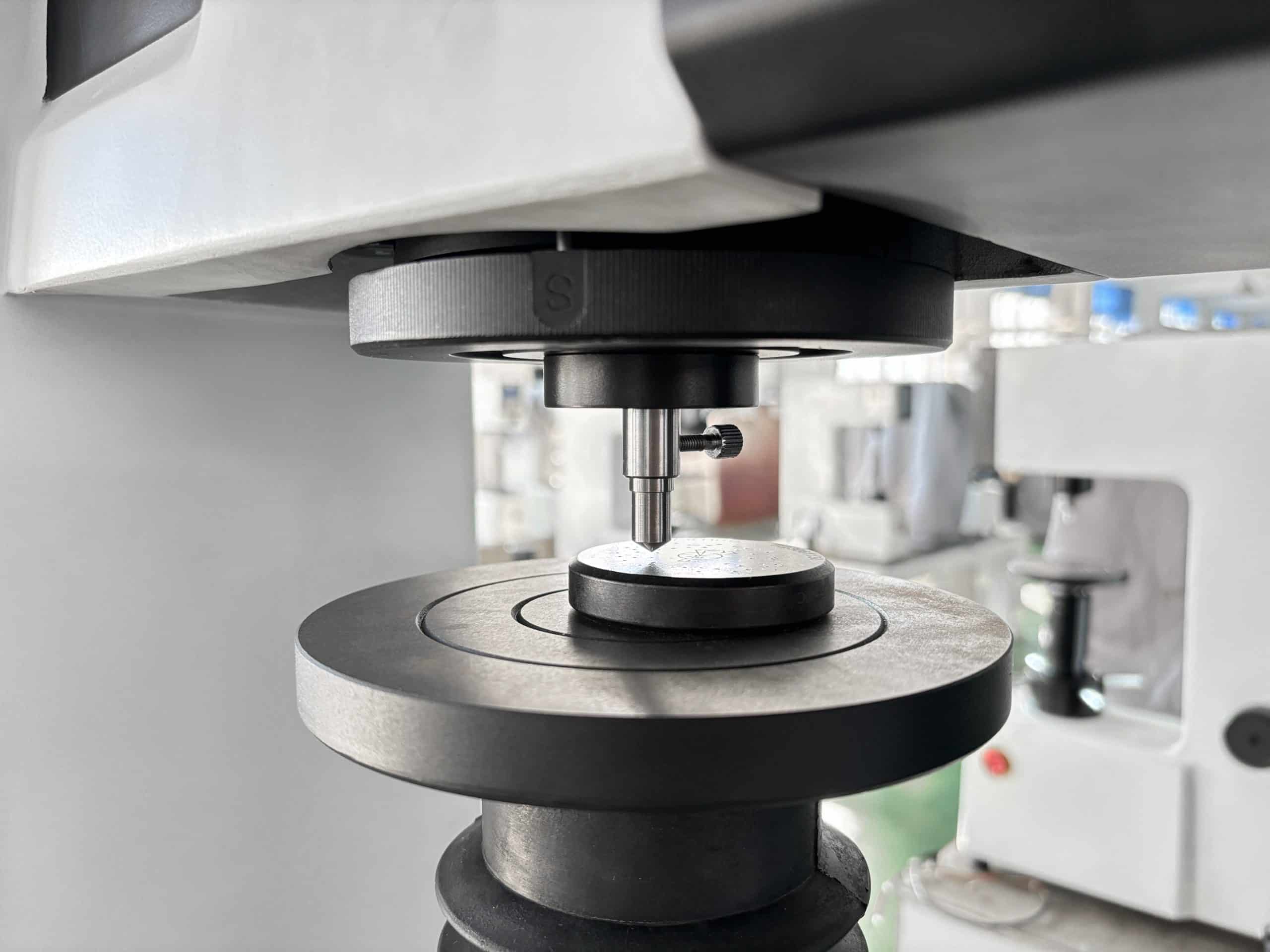
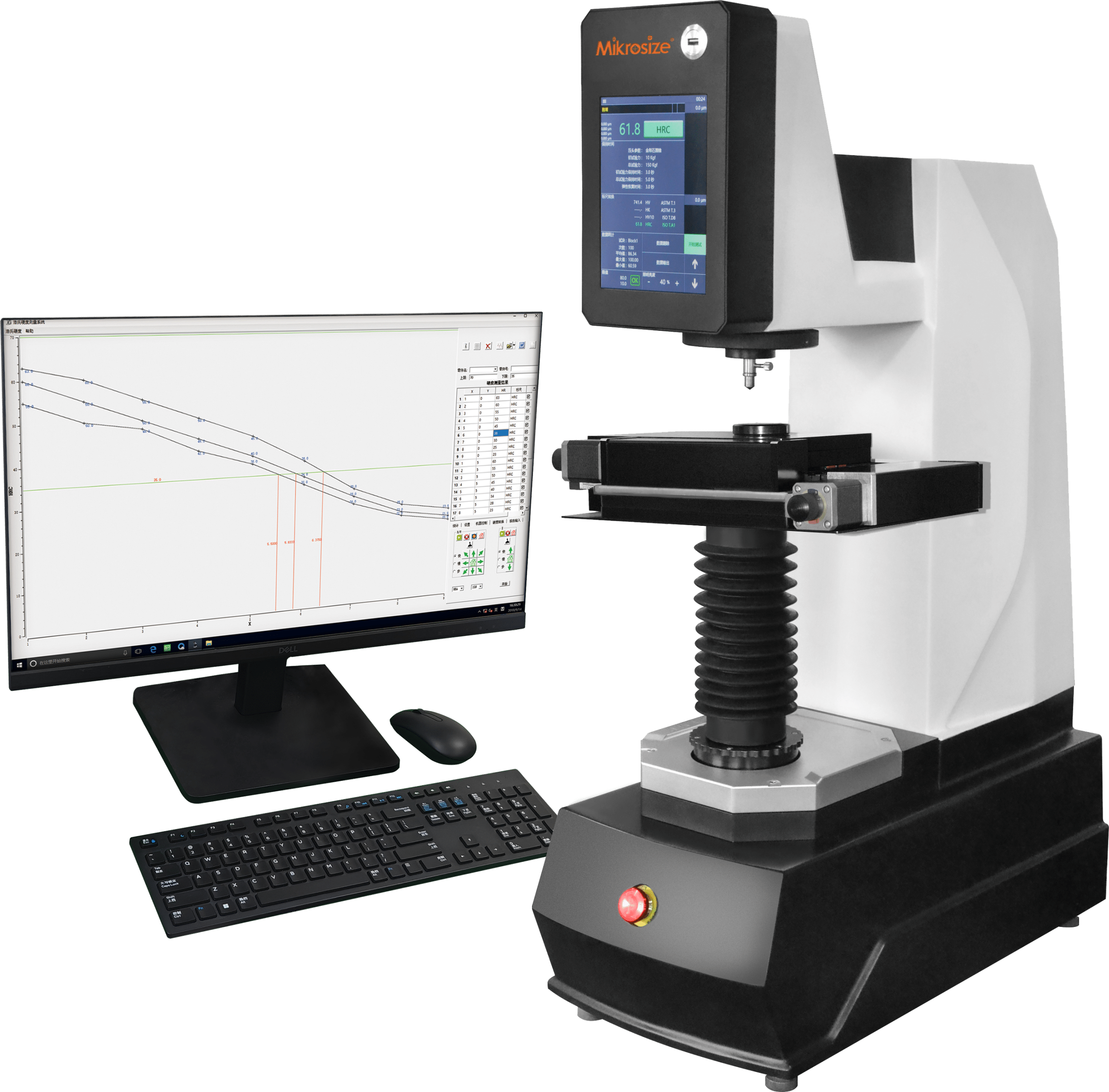
For high-volume automotive component hardness inspection, experts recommend auto-loading digital Rockwell hardness testers with motorized load sequence and digital readout functions. Premium models deliver reading stability within ±0.1 HRC and eliminate human visual estimation error. Modern instruments support automatic calibration routines: operators place certified reference blocks, and the unit automatically compensates zero-point drift using built-in calibration curves.
3.2 Three-Tier Core Calibration System
Calibration is not a one-time task; it operates under a three-tier system: daily shift-based check, periodic formal calibration, and metrological traceability.
- Every-shift daily check: Run tests on two certified reference blocks covering high-and-mid hardness ranges. Document deviation values. Stop testing immediately for troubleshooting once offset exceeds ±1 HRC.
- Periodic formal calibration: Invite third-party metrology labs for comprehensive recalibration every quarter or half-year using certified force gauges and reference hardness blocks.
- Metrological traceability: All certified reference hardness blocks must carry valid national-level or internationally-recognized calibration certificates and stay within service expiry dates.
3.3 Data Output & Traceability Setup
Modern digital Rockwell hardness testers are equipped with USB or RS232 communication ports. QC software logs individual indent hardness values, operator ID, timestamp, and workpiece batch codes. This feature forms the critical bridge connecting raw inspection data, quality reports and continuous heat-treatment-process optimization, fully satisfying IATF 16949 traceability requirements.
4. Standardized End-to-End Application Workflow
This field-proven workflow originates from gear-manufacturing production lines and fits sampling inspection or full inspection for most automotive machined components.
Step 1: Workpiece & Sample Preparation
- Surface conditioning: Remove burrs, oil stains and scale. Control surface roughness at Ra ≤1.6 μm to guarantee clear indent edges.
- Thickness rule: Workpiece thickness should be at least 10× indentation depth to avoid substrate interference on final readings.
- Secure clamping: Deploy dedicated V-blocks or magnetic specimen stages to eliminate workpiece shifting during indentation.
Step 2: Instrument Warm-up & Method Validation
- Power-on pre-heating for 10 minutes, especially under low-temperature winter workshop conditions for stable electronic-sensor performance.
- Select certified reference hardness blocks with hardness close to target-part nominal values. For parts measured at 55-60 HRC, pick reference blocks rated 56-60 HRC.
- Complete 5 successive indent tests on reference blocks and calculate average reading:
- Pass condition: average deviation versus block nominal value within ±0.5 HRC.
- Software offset compensation required: deviation sits within ±1.0 HRC.
- Stop testing: deviation goes beyond ±1.0 HRC; inspect diamond indenter damage and force-spring fatigue.
Step 3: Production-Floor Hardness Testing
- Select 3-5 valid test positions for each workpiece and keep test surfaces horizontal.
- Capture and store readings via auto-printing or QC-system entry.
- For each production batch, add extra sampling quantity if single-part reading diverges more than 2 HRC from batch average hardness.
Step 4: Result Review & Dispute Resolution
- QC supervisors re-verify 10-20 % of total test points. Cross-validate results with a second calibrated hardness tester or portable Leeb hardness meter.
- When measurement disputes occur, forward samples to lab for Vickers micro-hardness testing on identical surface zones as authoritative cross-reference.
Step 5: Data Archiving & Quality Traceability
- Generate batch-specific inspection reports including instrument ID, operator name, workpiece number, reference-block batch & expiry date, plus calibration timestamps.
- Upload datasets to MES / ERP quality modules. During customer complaint investigations or process tuning, quality staff can rapidly retrieve full hardness-testing context and corresponding operator records.
5. Critical Technical Notes for Automotive Hardness QC
- Pre-load and major-load dwell-time control: Standard pre-load hold time sits at 3-5 seconds; major-load dwell lasts 5-8 seconds. Insufficient dwell creates incomplete elastic recovery and falsely high readings. Over-long dwell triggers metal plastic flow and lower-than-actual hardness numbers. Fix timing parameters within site-specific SOP work instructions to cut operator-driven variance.
- Reference-block service-life management: A reference hardness block accumulating more than 500 indentations risks surface work-hardening and pit formation, invalidating certified nominal values. Log activation dates and total indent counts for each block, and arrange advance replacement once deviation enters warning thresholds.
- Diamond indenter inspection: Minor chipping or wear over 10 % on the 0.2 mm tip radius of a diamond indenter distorts indent-depth data significantly. Visual checks alone cannot detect subtle degradation. Perform optical-microscope tip inspections every six months. Quick-change indenter holders reduce re-calibration overhead after indenter swap-outs.
- Vibration and ambient-temperature mitigation: Stamping and welding operations produce 1-50 Hz ground vibration in automotive workshops that interferes indent-depth acquisition. Install hardness testers on anti-vibration pads or locate QC stations away from heavy stamping presses. Maintain lab environment at 23±5 °C and relative humidity ≤65 %.
- Non-editable timestamp-locked inspection data: Immutable logged test records satisfy IATF 16949 anti-tampering data requirements and lower audit-non-conformity risks.
- Operator qualification certification: Even automated testers rely on human judgement for workpiece placement and test-point selection. Organize periodic theoretical assessment and hands-on proficiency comparison for all QC technicians.
6. Application Boundaries of Different Hardness-Tester Solutions
Tester Type | Strengths | Suitable Scenarios | Limitations |
Automatic digital bench-top Rockwell hardness tester | Excellent repeatability, automatic data output | QC laboratories, dedicated high-frequency production-floor stations for gears and powertrain parts | Requires stable mains power supply |
Portable Rockwell hardness tester | Convenient for large-size components such as axles and crankshafts | Spot-check on-shop-floor large workpieces | Strict demand for flat workpiece surfaces; typical accuracy ±1-2 HRC |
Manual bench-top Rockwell hardness tester | Low capital cost | Low-frequency sampling inspection | Heavy operator-skill dependency; higher human-error probability |
Reference-grade metrological Rockwell hardness tester | Ultra-high measurement stability | Corporate central metrology labs, third-party calibration institutes | Not built for daily mass-production inspection |
Recommendation: Deploy automatic digital bench-top Rockwell hardness testers for high-priority heat-treatment processes. Use portable testers for quick on-site screening, and reserve reference-grade machines for metrology cross-checking. The three-tier setup delivers complete hardness-validation coverage.
7. Real-World Case Study: Transmission-Gear Heat-Treatment Workshop
A gear workshop manufactures roughly 800 transmission gears daily and requires batch sampling inspection for tooth-surface hardness with target window 58-62 HRC.
Original Issues
Two QC operators used hardness testers from different brands. Dwell-time parameters were inconsistent. Reference hardness blocks operated for 12 months without replacement and lacked calibration logs. Complex gear-tooth geometry created inconsistent test-point selection and poor-data reproducibility.
Solution Configuration
- Two automatic digital Rockwell hardness testers equipped with gear-specific V-clamps and magnetic specimen bases.
- Mandatory pre-shift validation routine: test five indent points on high-hardness and mid-hardness reference blocks per shift and maintain calibration logs. Trigger comparative troubleshooting when inter-instrument reading difference exceeds 0.5 HRC.
Business Value Realized
- Transition from manual paper logs to centralized electronic storage linking gear batch numbers and hardness datasets.
- Supervisors can review daily calibration logs rapidly to spot instrument drift or expired reference blocks.
- Full traceability of test timestamps, operators and reference-block batches during customer-claim investigations.
FAQ Section
Q1: Why do day-shift and night-shift operators get different HRC readings with the same Rockwell hardness tester?
A: The primary causes are inconsistent pre-load dwell-time, varied indent-point positioning, different zero-point-calibration frequency and worn reference-block surfaces. Standardized SOP documents, mandatory every-shift reference-block validation and operator qualification assessments mitigate most of these deviations.
Q2: How often should I perform formal calibration for Rockwell hardness testers under IATF 16949?
A: Third-party metrological calibration is suggested every 3-6 months. In addition, every-shift reference-block verification remains compulsory as part of daily QC activities, independent of formal third-party calibration cycles.
Q3: Can I keep using reference hardness blocks after hundreds of indent marks appear on the surface?
A: Not recommended. Over-used reference blocks develop surface work-hardening and pits. Record cumulative indent counts for each block. Replace the block once readings drift into warning thresholds, even before printed expiry dates.
Q4: What do I do when Rockwell hardness test results generate disputes between suppliers and OEM customers?
A: Re-check sample surface preparation and instrument-calibration records first. Complete cross-validation via Vickers micro-hardness testing on identical sample zones, which serves as widely-accepted authoritative verification within automotive-supply chains.
Q5: Is a portable Rockwell hardness tester acceptable for formal batch release inspection for transmission gears?
A: Portable units suit on-site preliminary screening. For formal batch-release decisions for safety-critical powertrain gears, use bench-top automatic Rockwell hardness testers with full metrological traceability.
Conclusion
For automotive component manufacturers, Rockwell hardness-tester calibration procedures are not merely compliance documents written for external audits; they form the logical backbone of day-to-day quality-control activities. The closed-loop workflow outlined in this blog, covering sample conditioning, instrument validation, production-floor testing and immutable data archiving, delivers consistent and defensible hardness results for quenched and carburized steel gears, bearing parts and other heat-treated automotive components. Equipment selection should prioritize workpiece characteristics, target hardness scales, shop-floor operating conditions, measurement repeatability and end-to-end traceability rather than focusing only on standalone technical specifications.
Implementing simple, every-shift reference-block verification delivers fast-improvement outcomes with minimal investment. When building or upgrading your hardness-testing laboratory, partnering with trusted metrology suppliers such as Mikrosize helps automotive quality teams deploy complete testing workflows, standardized operator training resources and long-term instrument-calibration support. Mikrosize’s comprehensive lineup of digital Rockwell hardness-testing instruments complies with ISO 6508 and ASTM E18 standards, empowering automotive-supply-chain enterprises to meet strict IATF 16949 traceability and accuracy requirements for metal-hardness quality assuranceMikrosize