
The UT-150 Ultrasonic Flaw Detector from Mikrosize is a portable industrial non-destructive testing device built on an ARM+FPGA hardware architecture. It combines a 5.7-inch HD IPS color display, IP65 protection rating, a 1.13 kg body, and up to 12 hours of battery life. With a 0–15 m detection range for steel components, it supports DAC/AVG curves, weld cross-section display, B-scan imaging, and crack height measurement—making it suitable for boilers, steel structures, rail transit, metallurgy, and petrochemical inspection.
1.Preparation and Connection
Before powering on, connect the probe to the BNC/LEMO dual-type probe socket. The UT-150 supports separate T transmit and R receive connections. For charging or data transfer, use the DC 9 V power input or the dual USB ports—one for USB storage and one for USB data communication. The ergonomic housing is water- and oil-resistant, with a rubber anti-slip protective boot and a hand strap for one-handed grip. The dual-damping swivel stand allows multi-angle inspection indoors and outdoors.
2. Power-On and Basic Settings
Press and hold the power key for about two seconds to turn on the instrument. The 5.7-inch HD IPS color display offers 640×480 resolution and a 60 Hz refresh rate, with brightness adjustable from 20% to 100%. Use the shortcut keys to enter the Basic function group and set language, units, grid mode, screen brightness, and UI color scheme. The instrument provides four selectable UI color schemes for different lighting conditions.
3. Probe Settings and Automatic Calibration
Enter the Probe function group to select the probe type and set frequency, pulse voltage, pulse width, damping, and zero offset. The UT-150 supports automatic probe calibration, which simplifies setup and helps maintain stable accuracy. Gain adjustment ranges up to 110 dB, with selectable steps of 0.1 dB, 1 dB, 2 dB, or 6 dB. Use the Auto Gain shortcut for automatic gain control when scanning.
4.Gate Adjustment and Scanning
The UT-150 provides dual independent gates A/B, supporting single-gate and dual-gate reading modes. Gate start, width, and height are adjustable, with gate height from 5% to 90%. Two trigger modes are available: peak trigger for peak echo reading and edge trigger for leading-edge reading. During scanning, hold the probe firmly and move it at a constant speed across the workpiece surface. The waveform display supports waveform fill, peak marking, echo coding for 1st–9th reflection echoes, independent gate color change, and gate widening/zooming.
5.DAC/AVG and Weld Inspection


For weld inspection, use DAC/AVG curves to evaluate lack of penetration and cracks. The weld cross-section display allows user-defined V-groove and other groove types, workpiece thickness, and probe offset distance, visually showing defect position in 2D. The AVG function automatically generates three equivalent curves for flat-bottom hole, large flat bottom, and short transverse hole reflectors, and displays the defect equivalent aperture diameter in real time. The instrument also supports B-scan imaging for visual defect morphology, with adjustable scan speed, height, and color. AWS D1.1 automatic rating and tip diffraction crack height measurement are included for standards-based evaluation.
6. Alarm and Measurement
The dual gates provide echo-entry and loss-of-echo alarms with synchronized red LED and buzzer indication. Real-time automatic calculation includes sound path, vertical depth, horizontal distance, echo amplitude, and equivalent dB/aperture size. Peak memory locks the maximum defect echo, helping users capture critical indications during scanning.
7.Data Recording and Export


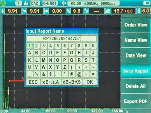
The UT-150 stores 500 channel setups and 1,000 PDF inspection reports, with data retained after power failure. Real-time screenshots save color or grayscale BMP images to a USB flash drive. PDF inspection reports are generated directly on the instrument and exported via USB flash drive; they can be opened and printed on a computer or mobile phone. Video recording captures the flaw detection waveform throughout inspection, with pause, fast-forward, and fast-rewind playback. A real-time clock (RTC) automatically attaches precise timestamps to all reports, recordings, and screen captures. Channels and reports can be batch-managed—single or all import/export, renaming, and deletion—and inspection parameters can be copied between instruments via USB flash drive.
8. Maintenance Notes
Regularly clean the device and probe to prevent dust and stains from affecting detection accuracy. Calibrate with a standard test block at intervals to maintain measurement reliability. When the instrument is not used for an extended period, store it properly to protect it from moisture and impact. Following these operation and maintenance steps helps the UT-150 deliver stable performance in laboratory and outdoor field environments.